CSolution Project Structure
This chapter outlines the structure of csolution project files that contain the build information of the software application.
- Project Examples and project templates help to get started with the tools.
- Software Layers provide reusable configurations and give projects a better structure.
- Directory Structure describes the overall directory structure of projects.
- Linker Script Management defines the available memory and controls the linker operation.
- Generator Support integrates configuration tools such as STM32CubeMX or MCUXpresso Config.
- Run and Debug Configuration explains how to configure debug adapters such as CMSIS-DAP or J-Link.
- West Build System Integration allows to manage Zephyr applications in context with a csolution project.
- MLOps Integration describes how to generate an ML model layer and integrate it into an application.
Overview of Operation
The generated build information is the interface between the common project information and development tools. It allows build systems, smart editor features, static code analysis and test tools, programming tools, debuggers, trace tools, and CI/DevOps workflows to use the same resolved application and target configuration.
The diagram below outlines the operation of the csolution command convert that processes the csolution project with one or more context configurations for an application.
Tip
- Project Examples show different project types and provide templates for user projects.
- Build Process Overview explains the complete end-to-end build process.
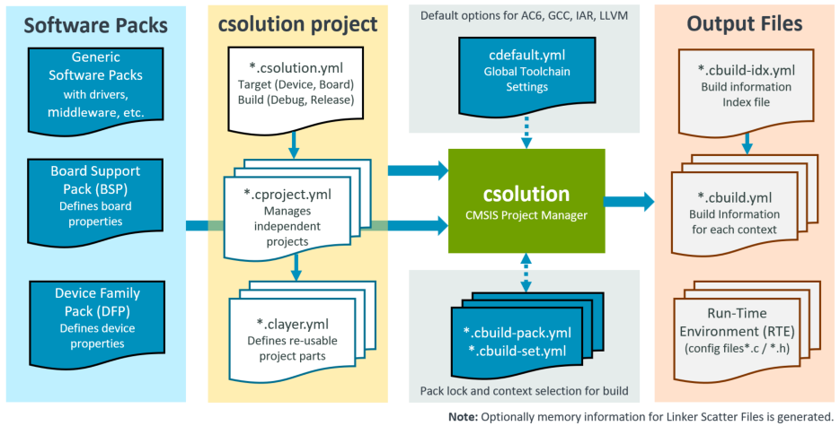
| Input Files | Description |
|---|---|
| Generic Software Packs | Provide re-usable software components that are typically configurable towards a user application. |
| DFP Software Pack | Device-related information (including memory sizes) for the tool configuration. |
| BSP Software Pack | Board specific configuration (i.e. additional memory resources). |
| cdefault.yml | When enabled with cdefault:, setup of toolchain specific controls and pre-defined toolchains. |
| *.csolution.yml | Complete scope of the application with sub-projects. Defines target and build types. |
| *.cproject.yml | Content of an independent build step (linker or library archiver run). |
| *.clayer.yml | Set of source files along with pre-configured components for reuse in different applications. |
| Input/Output Files | Description |
|---|---|
| *.cbuild-pack.yml | Exact list of the packs that are used by the application; enables reproducible builds as it locks the pack versions. |
| Output Files | Description |
|---|---|
| *.cbuild-idx.yml | Index file of all *.cbuild.yml build descriptions; contains also overall information for the application. |
| *.cbuild.yml | Build description of a single *.cproject.yml input file for each context. |
| *.cbuild-run.yml | Configuration file of a csolution project to run and debug an application on a target. |
| *.cbuild-mlops.yml | Information file for MLOps integration that is enabled with mlops: in the *.csolution.yml file. |
| Run-Time Environment (RTE) | Contains the user-configured files of a project along with the RTE_Components.h inventory file. |
| Linker Script Files | Header file that describes the memory resources. |
To generate the build information of an application project, the csolution command convert executes the following steps:
-
Read Input Files (csolution project and Software Packs)
-
Process each project context (defined by a target-set or the option:
--context): -
Generate Output Files:
- Update configuration files in RTE directory (disable with option:
--no-update-rte). - Print results of software component dependency validation.
- Update configuration files in RTE directory (disable with option:
Source Code of Software Packs
Software packs and the related components: allow you to share and reuse code. The content of a software pack is, therefore, read-only (with the exception of configuration files that are copied to the RTE directory) as these source code files should not be modified by a user.
The benefit is a clean project directory that only contains the user code and configuration files for components:. This keeps a repository small and makes it easy to upgrade to a new pack version.
Note
- During the development of a software pack, you may install a repository, which contains the source of the software pack.
- You may copy the content of a software pack to your project workspace and provide a path to the pack.
Project Examples
GitHub repositories
The following repositories provide several working examples:
| Repository | Description |
|---|---|
| csolution-examples | Contains several getting started examples that show single-core, multi-core, and TrustZone setup as well as how to use a generator (CubeMX). |
| github.com/Arm-Examples | Contains many examples that include CMSIS-Toolbox setup. |
The section below explains the overall concepts considered by the csolution Project Manager based on examples.
Template Projects
The CMSIS-Toolbox Templates show the file structure for several types of csolution projects and may be used as a starting point for an application. Refer to Create Applications for the workflow to select target hardware and software packs, add software components, and build the application.
Minimal Project Setup
A minimal application requires two files:
-
Sample.csolution.ymlthat defines a target type with board or device. It includes a project and selects a compiler. -
Sample.cproject.ymldefines the files and software components that are translated into an image.
Note
When no packs: are specified in csolution project files, the tools use the latest version of the installed packs.
Simple Project: Sample.csolution.yml
solution:
  cdefault:                                   # use default setup for toolchains
  compiler: AC6                               # select the compiler to use

  packs:                                      # explicit pack selection may be omitted
    - pack: NXP::K32L3A60_DFP@16.0.0          # specify DFP
    - pack: NXP::FRDM-K32L3A6_BSP@16.0.0

  target-types:
    - type: FRDM-K32L3A6
      board: FRDM-K32L3A6

  build-types:
    - type: Debug                             # toolchain options for 'debug'
      debug: on
      optimize: debug

    - type: Release                           # toolchain options for 'release'
      debug: off
      optimize: balanced

  projects:
    - project: ./Sample.cproject.yml
Simple Project: Sample.cproject.yml
project:
  packs:
    - pack: ARM::CMSIS                        # specify additional packs

  groups:
    - group: App
      files:
        - file: ./main.c

  components:
    - component: CMSIS:CORE
    - component: Device:Startup
Context
A context is defined in the *.csolution.yml file by projects:, target-types:, and build-types:. It identifies a configuration with project-name, build-type, and target-type and is used on various places in the CMSIS-Toolbox.
The following context refers to the example above and selects the project: Sample.cproject.yml with build-type: Debug and target-type: FRDM-K32L3A6:
Sample.Debug+FRDM-K32L3A6
The context allows you to refer to each possible build combination that, by default, uses a different output directory. A context may be partly specified in many places.
The target-set defines a combination of projects (that belong to the same target type) along with debug configuration and is useful when an application is composed of multiple related projects.
Toolchain Agnostic Project
Generic Translation Control settings enable projects that work across the range of supported compilers (AC6, GCC, IAR, CLANG). The Translation Control settings are mapped to specify compiler controls by the build tools.
cdefault.yml
The cdefault.yml file contains a common set of compiler-specific settings that select reasonable defaults with misc: controls for each compiler. The cdefault: node in the *.csolution.yml file enables the usage of this file. The directory <cmsis-toolbox-installation-dir>/etc contains a cdefault.yml file that is used when no local copy of the cdefault.yml file is provided.
Note
- For reproducible builds, place a local copy of
cdefault.ymlin the directory containing the*.csolution.ymlfile. - Keep the default configuration options in
cdefault.ymlunless the project requires different settings. - For IAR,
-eenables embedded language extensions, including CMSIS attributes such as__weak,__packed,__noreturn, and__aligned.
Example:
default:

  misc:
    - for-compiler: AC6
      C-CPP:
        - -Wno-macro-redefined
        - -Wno-pragma-pack
        - -Wno-parentheses-equality
        - -Wno-license-management
      C:
        - -std=gnu11
      ASM:
        - -masm=auto
      Link:
        - --entry=Reset_Handler
        - --info=summarysizes
        - --summary_stderr
        - --diag_suppress=L6314W

    - for-compiler: GCC
      C-CPP:
        - -masm-syntax-unified
        - -fomit-frame-pointer
        - -ffunction-sections
        - -fdata-sections
      C:
        - -std=gnu11
      Link:
        - --specs=nano.specs
        - --specs=nosys.specs
        - -Wl,-print-memory-usage
        - -Wl,--gc-sections
        - -Wl,--no-warn-rwx-segments   # suppress incorrect linker warning

    - for-compiler: CLANG
      C-CPP:
        - -fomit-frame-pointer
        - -ffunction-sections
        - -fdata-sections
      C:
        - -std=gnu11
      Link:
        - -Wl,-print-memory-usage
        - -Wl,--gc-sections

    - for-compiler: IAR
      C-CPP:
        - -e
        - --dlib_config DLib_Config_Full.h
Compiler Selection
There are two ways to select a toolchain:
- An explicit
compiler:selection in the*.csolution.ymlproject file:
solution:
  cdefault:           # use the cdefault.yml file with toolchain specific controls
  compiler: AC6       # select Arm Compiler
  :
- The command line option
--toolchainof thecbuildorcsolutiontool overwrites anycompiler:definition in the csolution project files.
cbuild Hello.csolution.yml --toolchain GCC
The solution-level compiler-alias: node accepts software components and pack conditions defined for compatible compiler toolchains while retaining the selected compiler for the build.
Tip
- Toolchain agnostic example projects do not contain a
compiler:selection in the*.csolution.ymlproject file. - Instead the
select-compiler:node list the compilers that this csolution project is tested with. The VS Code extension Arm CMSIS Solution adds thecompiler:node based on the installed compiler in your environment.
Reproducible builds
Reproducible builds are supported by the *.cbuild-pack.yml file that is created and read by the csolution project manager. This file:
- Records the exact list of the pack versions used during the creation of an application.
- Ensures that pack versions do not change during development, even when new packs are installed on the host computer, for example, to develop other applications.
Note
- The *.cbuild-pack.yml file should be committed to a repository to ensure reproducible builds.
- The
cbuildoption--frozen-packschecks that the *.cbuild-pack.yml file exists and reports an error if any pack is changed or not available. - Before updating, use
csolution check pack-updatesto review available versions and release notes. Then change the applicablepack:requirement or remove only that pack'sresolved-pack:entry from*.cbuild-pack.ymland runcbuild setup <solution>.csolution.yml --update-rteorcsolution update-rte. Review the resulting configuration-file changes before committing the updated*.cbuild-pack.ymland RTE files. Deleting the entire file resolves every pack again and should be reserved for an intentional full refresh.
Repository Contents
To support reproducible builds, the following files should be committed to a repository of a version control system.
- All user source code files.
- All csolution project files (
cdefault.yml,*.csolution.yml,*.cproject.yml, etc.). - All files in the RTE directory
- Ensure that there are no files with the extension .update@ as this indicates that configuration files are not up-to-date due to updated software packs.
- The file
*.cbuild-pack.ymlto allow reproducible builds.
Configure Related Projects
A solution is the software view of the complete system. It combines projects that can be generated independently and therefore, manages related projects. It may also be deployed to different targets during development as described in section Software Layers.
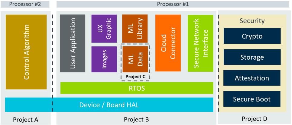
The picture below shows a system that is composed of:
- Project A that implements a time-critical control algorithm running on an independent processor #2.
- Project B is a cloud-connected IoT application with Machine Learning (ML) functionality.
- Project C is the separate data model of the ML algorithm, allowing independent updates.
- Project D implements the device security (for example, with TF-M that runs with TrustZone in secure mode).
In addition, such systems may have a boot-loader that can also be implemented as another independent project.
At the level of the *.csolution.yml file, the target-types: and build-types: are managed so that a common set is available across all *.cproject.yml files in the system.
-
target-types:typically describe a different hardware target system. -
build-types:typically describe a build variant of the same hardware target system.
Both types are used for peripherals and the same hardware configuration but may compile a different variant (i.e. with test I/O enabled) of an application.
Related Projects: iot-product.csolution.yml
solution:
   :                            # setup not shown

  target-types:
    - type: Board
      board: NUCLEO-L552ZE-Q    # uses device defined by the board

    - type: Production-HW
      device: STM32U5X          # specifies device

  build-types:
    - type: Debug
      optimize: none
      debug: on

    - type: Release
      optimize: balanced
      debug: on

    - type: Test
      optimize: size
      debug: on

  projects:
    - project: ./security/TFM.cproject.yml           # Project D: Only generated for build type: Release
      for-context: .Release
    - project: ./application/MQTT_AWS.cproject.yml   # Project B
    - project: ./mldata/Model.cproject.yml           # Project C
    - project: ./bootloader/Bootloader.cproject.yml  # Not generated for target type: Board
      not-for-context: +Board
    - project: ./processor2/Control.cproject.yml     # Project A
Working with target-set
A target-set: specifies the context types and additional images that are combined into an application. The following example defines the Run and Debug configurations for the iot-product.csolution.yml application that is shown above using the target-set: node.
Note
Run and Debug Configuration shows how a debugger: is specified for a build variant that is defined with target-set:.
solution:
   :                            # setup not shown

  target-types:
    - type: Board
      board: NUCLEO-L552ZE-Q    # uses device defined by the board
      target-set:
        - set:                  # default set for this target
          images:
            - project-context: MQTT_AWS.Debug
            - project-context: Control.Debug

    - type: Production-HW
      device: STM32U5X          # specifies device
        - set:                  # default set for this target
          images:               # all projects as release version
            - project-context: Bootloader.Release
            - project-context: TFM.Release
            - project-context: MQTT_AWS.Release
            - project-context: Model.Release
            - project-context: Control.Release
        - set: Debug            # alternative set for debugging on Production-HW
          images:               # projects and images required for debugging
            - image: Bootloader_Dummy.hex           # use an dummy image
            - project-context: TFM.Release
            - project-context: MQTT_AWS.Debug       # load debug build
            - image: Model_Test.hex                 # use a test Model
Using the Build Tools option --active (or -a) generates the different build variants:
cbuild iot-product.csolution.yml -a Board                   # target-type Board with default set
cbuild iot-product.csolution.yml -a Production-HW           # target-type Production-HW with default set
cbuild iot-product.csolution.yml -a Production-HW@Debug     # target-type Production-HW with Debug set
When --active <target-type> omits the target-set name, the unnamed target-set is selected when available; otherwise, the first named target-set is used. If the selected target-set has no project-context entries, or the target type defines no target-set, the default context is the first project with the first build type and the selected target type. Specifying --active <target-type>@<target-set> selects that set explicitly and uses the same default-context rule when it has no project-context entries. An empty selection (--active "") uses the first target type and its first target-set, if present, with the same fallback to the default context.
Load Attributes
Load attributes are typically used when testing a bootloader or a bank-swapping mechanism. In such cases, often only symbol information is required. Using load-offset: (supported by pyOCD) allows loading the content of a binary image at a different physical address.
The example STM32_LiveUpdate uses swappable Flash banks to switch to a new firmware version that is initially programmed into the inactive Flash bank. The binary image of the new firmware version uses load-offset: (pyOCD only). The ELF symbol information is loaded separately without the offset so that the symbolic information is available for debugging.
solution:
  compiler: AC6
  target-types:
    - type: Version_1
      device: STM32L476RGTx
      target-set:
        - set:
          images:
            - image: $bin(test_v1)$       # binary file of project test_v1
              load: image
              load-offset: 0x08080000     # load with an offset into Flash
            - project-context: test_v1    # load from project test_v1
              load: symbols               # load only symbol information
          debugger:
            name: ST-Link@pyOCD
            port: 3333
            protocol: swd
            clock: 4000000
  projects:
    - project: test_v1.cproject.yml
External Tools and Build Order
The executes: node integrates CMake scripts and external tools. The input: and output: lists typically refer to files and therefore define the build order of projects:
- When
input:contains files that are the output of acproject.yml, this project part is built first. - When
output:contains files that are the input of acproject.yml, theexecute:node is built first.
Example:
The KeyGenerator tool builds the file keys.c, which is added as a source file: for other projects. Using cbuild My.csolution.yml --active <target-type>[@<target-set>] starts the build process of the application and runs the KeyGenerator before building projects that use the source file keys.c as input.
Note
Using cbuild with the option --context does not run execute: nodes as it triggers project builds only. Use an application build, optionally selected with --active.
solution:
    :
  executes:
    - execute: GenKeys                      # is a CMake target name
      run: KeyGenerator -k $input(0)$ -p $input(1)$ -o $output$
      input:
        - $SolutionDir()$/keyfile.txt       # input(0) contains key in text format
        - $SolutionDir()$/passcode.txt      # input(1) contains passcode in text format
      output:
        - $SolutionDir()$/keys.c            # output keys source file (input to other projects)
Project Dependency
An access sequence that refers to the output of another project also impacts the build order.
Example:
The access sequence $cmse-lib(Project_S)$ includes the secure entry library of Project_S. Hence, Project_S is built before the non-secure project part of the application.
project:                                 # Non-secure project
    :
  groups:
    - group: CMSE Library
      files:
        - file: $cmse-lib(Project_S)$    # Secure part of an application
Use a Prebuilt Secure Image
A non-secure project may use a secure image that is not part of the active target set. This is useful when the secure application is built and released separately. The non-secure application typically needs two matching artifacts:
- The secure image, for example a HEX file that is loaded together with the non-secure application.
- The CMSE import library that describes the secure callable interface and is linked with the non-secure project.
List the non-secure project before the prebuilt secure image in the target set so that debuggers and simulation models load the executable before overlaying the HEX file:
solution:
  target-types:
    - type: AVH-NS-only
      target-set:
        - set: Debug
          images:
            - project-context: Project_NS.Debug
            - image: out/Project_S/AVH/Debug/Project_S.hex
              load: image
Reference the corresponding CMSE import library as a regular file in the non-secure project:
project:                                 # Non-secure project
  groups:
    - group: CMSE Library
      files:
        - file: ../out/Project_S/AVH/$BuildType$/Project_S_CMSE_Lib.o
          for-context: +AVH-NS-only
Unlike the $cmse-lib(Project_S)$ access sequence, these file references do not establish a project dependency or
build the secure project. Create the secure artifacts before building the non-secure context. Both builds must use
compatible build types, toolchains, memory layouts, and secure callable interfaces.
> cbuild My.csolution.yml --context Project_S.Debug+AVH --toolchain AC6
> cbuild My.csolution.yml --context Project_NS.Debug+AVH-NS-only --toolchain AC6
The SimpleTrustZone example demonstrates this workflow and provides target sets for running the complete application and the non-secure project with an existing secure image.
Generate Library
A library is a collection of pre-build source code that is stored in a single archive file. A library is typically used by many applications and is compiled for a series of devices that share the same processor. It uses fixed compiler options and does not expose source code. It keeps projects smaller and reduces build time by avoiding repeated compilation of the same sources.
A library may use APIs from other software components. In this case, you typically want to use the component header files, but exclude the component source files from the generated library archive. The build-scope: attribute of a component: to controls whether component source files are compiled as part of the current build (default: include for image builds, exclude for library builds).
Example:
The Library.csolution.yml file selects the toolchain (compiler: AC6), the target processor and a the build options.
The related Library.cproject.yml file sets the output to a library archive (output: type: lib), declares the required packs/components, and lists the source files that are compiled into the library.
Library.csolution.yml file:
solution:
  cdefault:                              # Default compiler configuration
  packs:
    - pack: ARM::Cortex_DFP              # Generic Device Pack

  compiler: AC6

  target-types:
    - type: Cortex-M4                    # Create for Cortex-M4 processor with FPU
      device: ARMCM4

  build-types:
    - type: Library
      optimize: size
      debug: off

  projects:
    - project: Library.cproject.yml
Library.cproject.yml file:
project:
  output:
    type: lib    # generate library

# List packs and components that the library depends on
  packs:
    - pack: ARM::CMSIS
    - pack: ARM::CMSIS-RTX

  components:
    - component: CMSIS:CORE
    - component: CMSIS:RTOS2:Keil RTX5&Source
      build-scope: include              # include RTX source code in library

# List source files that are included in the library
  groups:
    - group: Library
      files:
        - file: myfile1.c
        - file: myfile2.c
Tip
The CMSIS-RTX project includes a Library directory with the setup for multiple library variants. The software pack uses conditions in the pack description file (*.pdsc) to select the correct library variant for Arm Cortex processors and compiler variants.
Software Layers
Software layers collect source files and software components along with configuration files for reuse in different projects. Software Layers gives projects a better structure and simplifies:
- Development flows with evaluation boards and production hardware.
- Evaluation of middleware and hardware modules across different microcontroller boards.
- Code reuse across projects, i.e. board support for test-case deployment.
- Test-driven software development on simulation model and hardware.
Simple Example:
This example uses a layer to include an RTOS kernel. The file MyProject.cproject.yml includes the file RTOS.clayer.yml using the layers: node:
project:
  groups:
    - group: App
      files:
        - file: ./main.c

  components:
    - component: CMSIS:CORE
    - component: Device:Startup

  layers:
    - layer: ../Layer/RTOS.clayer.yml    # Add RTOS kernel
The RTOS.clayer.yml file defines the kernel along with configuration settings.
layer:
  description: RTX RTOS with configuration settings

  packs:
    - pack: ARM:CMSIS-RTX

  components:
    - component: CMSIS:RTOS2:Keil RTX5&Source
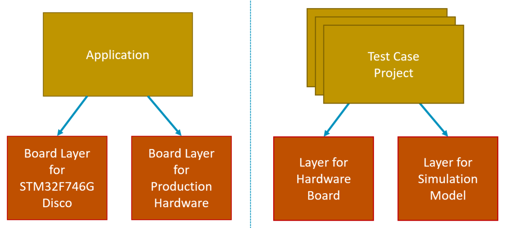
The diagram below shows two different scenarios, which are explained in the following sections.
Target Production Hardware
Software development frequently starts on evaluation boards. Using a board layer simplifies re-targeting to production hardware. The following *.csolution.yml file exemplifies the concept. A software developer starts with a board layer for the evaluation board in the folder MyBoard. Once the production hardware is available, this layer is copied to a different folder (i.e. MyHardware). As both layers are independently managed, the configuration of the MyHardware layer can be modified, for example, to target different devices, pin layout, or peripheral configurations.
In the *.csolution.yml project, the layer is defined using a variable. By changing the target-type during the build process, the software developer can continue to use the evaluation board or target the production hardware.
solution:
  cdefault:
  compiler: AC6

  target-types:
    - type: EvalBoard
      board: STMicroelectronics::B-U585I-IOT02A:Rev.C
      device: STMicroelectronics::STM32U585AIIx
      variables:
        - Board-Layer: $SolutionDir()$/MyBoard/Board.clayer.yml

    - type: ProductionHW
      device: STMicroelectronics::STM32U575AIIx    # uses a different device
      variables:
        - Board-Layer: $SolutionDir()$/MyHardware/Board.clayer.yml

  build-types:
    - type: Debug
      debug: on
      optimize: debug
    - type: Release
      debug: off
      optimize: balanced

  projects:
    - project: HID/HID.cproject.yml
Tip
- The MDK-Middleware examples are structured in this way. Start with a board layer that is provided in several Board Support Packs.
- Another project that extends this concept to hardware shields is the Sensor-SDK-Example.
Test Case Project
Modern software design mandates for test-driven development that utilize DevOps or CI principals. Arm Fixed Virtual Platform (FVP) simulation models allow test automation without target hardware.
However, in some cases, tests should also be performed on physical hardware. A test case project may, therefore, contain targets for simulation and physical hardware. The csolution project format allows multiple test projects to be combined to validate different parts of the application.
solution:
  cdefault:
  compiler: GCC
    :                              # pack definition not shown

  target-types:
    - type: Board
      board: NUCLEO-L552ZE-Q
      variables:
        - Board-Layer: ./Board/NUCLEO-L552ZE-Q/Board.clayer.yml

    - type: FVP
      board: VHT-Corstone-300      # FVP platform (appears as a board)
      variables:
        - Board-Layer: ./Board/Corstone-300/FVP.clayer.yml

  projects:
    - project: ./TestSuite1/TestCases.cproject.yml
    - project: ./TestSuite2/TestCases.cproject.yml
    - project: ./TestSuite3/TestCases.cproject.yml
Tip
- Several examples for Arm FVP simulation models show usage of csolution projects in CI workflows.
- The project AVH-MLOps-Main is a test project that shows retargeting to different processors using a layer.
- The project AWS_MQTT_Demo extends this concept with retargeting of an IP communication to virtual or physical hardware.
Configuration Settings
A software layer is a set of source files and pre-configured software components or source code that can be shared across multiple projects. To achieve this, the configuration files of a layer are stored within the directory structure of the software layer. This separate RTE Directory Structure allows that projects
can share a layer with common configuration settings.
Note
When using a generator, such as CubeMX or MCUxpresso, the output should be redirected as described under Configure Generator Output.
Software Layers in Packs
Software layers for reference applications may be published in software packs. For more information, refer to Pack Creation: Layers.
Directory Structure
This section describes how the csolution based project files should be organized to allow the scenarios described above. This section also gives guidelines for a directory structure.
Refer to Directory Control for information about configuring these directories.
Working Areas
The table below explains the different working area sections of an application project.
| Working Area | Access | Description |
|---|---|---|
| Project Area | RW | Contains user source code files managed by the user along with the project files (see next item). |
| Project files | RW | Created by a user or an IDE to describe the application project. |
| Component source code | RO | Content of software packs; the location is specified by the environment variable CMSIS_PACK_ROOT or the node pack: path in project files. |
| Component Configuration | RW | User-editable config files of software components that are copied to the RTE directory. |
| Generator artifacts | RO (see note) | Managed by domain-specific configuration tools such as STM32CubeMX or MCUXpresso. |
| Build artifacts | RW | Created during the build process for example by a compiler. |
Note
Some generators allow user modification of the generated files. For example, STM32CubeMX allows modification of source code between /* USER CODE BEGIN */ and /* USER CODE END */ and preserves this modification even when the STM32CubeMX regenerates the files.
Project Area
There are no strict rules on how to organize the project area that stores the user source code. However, the following guidelines apply:
- Each solution should have a distinct base directory. This directory contains the file
*.csolution.ymlwhich refers to the independent projects defined with*.cproject.ymlfiles.
Each project should have a distinct base directory. This directory contains the file *.cproject.yml, which defines the project's content. The project's source code might be grouped in subdirectories that are typically stored in this base directory. The configuration files of the software components are typically stored in a subdirectory with the name ./RTE.
- A
*.cproject.ymlmay refer to one or more software layers with*.clayer.ymlfiles. Each software layer should have a distinct base directory with a similar structure as a project. This base directory contains the file*.clayer.ymlthat defines the content of the software layer. It also contains the user source code (optionally organized in sub-directories) and the configuration files of software components that belong to this layer, typically stored in a sub-directory with the name./RTE.
RTE Directory Structure
The table below summarizes the overall directory structure and further details the ./RTE directory. The ./RTE directory contains the configuration information for software components and is managed by the csolution Project Manager. It contains:
- Configuration files of the software components. These files have
attr="config"in the PDSC-file of the software packs. Refer to PLM of Configuration Files for more information. - The file
RTE_components.hand pre-include files are generated based on the software packs' PDSC file information.
Note
The ./RTE directory structure is maintained by tools. You should not modify its structure. However, the complete directory should be committed to a repository of a version control system.
| Directory Structure | Content |
|---|---|
<csolution> |
Base directory that contains one or more *.csolution.yml files. |
<project> |
Each project has its own directory; this base directory contains the *.cproject.yml file. |
<project>/RTE/<Cclass> |
Configurable files for each component Cclass have a common directory. |
<project>/RTE/<Cclass>/<device> |
Configurable files for components that have a condition to a device are in a separate directory. |
<project>/RTE/<context-dir> |
Directory for RTE_components.h and pre-include files that are generated by the csolution Project Manager. |
<layer> |
Each layer has its own base directory; this directory contains the *.clayer.yml file. |
<layer>/RTE/<Cclass> |
Configurable files for each component Cclass have a common directory below the layer base directory. |
<layer>/RTE/<Cclass>/<device> |
Configurable files for components that have a condition to a device are in a separate directory below the layer base directory. |
The <context-dir> has the following format: _<build-type>_<target-type>.
Note
The <context-dir> is generated when RTE files are updated. Use cbuild setup <solution>.csolution.yml --update-rte to prepare or refresh these files for development, or add --update-rte to a cbuild invocation. Without this option, cbuild leaves the RTE directory unchanged. The directory naming is aligned with other tools that support the CMSIS-Pack system.
Output Directory Structure
By default, the following output directories and build information files are generated using the cbuild command.
| Output | Content |
|---|---|
./out/<project>/<target>/<build> |
Contains the final binary and symbol files of a project context. |
./out/<project>/<target>/<build>/<project>.<build>+<target>.cbuild.yml |
Build description generated for a project context. |
./out/<project>/<target>/<build>/compile_commands.json |
Compilation database generated by cbuild setup for Static Code Analysis. |
./out/<project>/<target>/<build>/compile_macros.h |
Compiler built-in macros referenced by the compilation database. |
./out/<solution>+<target>.cbuild-run.yml |
Programming and debugging description generated for the active target-set. |
The actual directories are controlled by output-dirs:. Tools should resolve these files through the references in <solution>.cbuild-idx.yml instead of constructing their paths.
Software Components
Software components are re-usable library or source files that do not require modification in the user application. Optionally, configurable source and header files are provided to allow the setting of parameters for the software component.
- Configurable source and header files are copied to the project using the directory structure explained above.
- Libraries, source, and header files that are not configurable (and need no modification) are stored in the directory of the software component (typically part of CMSIS_Pack_ROOT) and get included directly from this location into the project.
- An include path to the header files of the software component is added to the C/C++ Compiler control string.
Notes
- The command
cbuild setup <solution>.csolution.yml --update-rteprepares the build information and updates the files in the./RTEdirectory. - The
csolutioncommandupdate-rteonly updates the configuration files in theRTEdirectory. - A normal
cbuildinvocation does not change RTE configuration files. Add--update-rtewhen an update is required. - Using the option
--verboseoutputs additional version details.
PLM of Software Packs
Software packs evolve over time (bug fixes, new features, dependency and component updates). Checking the installed vs. available software pack versions helps you decide when to upgrade (or stay pinned) to keep builds reproducible and to avoid unexpected behavior changes caused by a pack update.
Use these steps to update packs and configuration files:
- Update available pack information:
cpackget update-indexupdates the public index and cached PDSC metadata. With--sparse, only the index is updated. - Install required packs:
cpackget addinstalls the requested pack and its dependencies. During an automatic index update, only the PDSC metadata required for these packs is refreshed. This does not change a project's resolved versions or RTE files. - Review available project updates:
csolution check pack-updatesreports newer versions and optionally their release notes. It does not modify the project. - Resolve project pack versions:
csolutionrecords exact versions in*.cbuild-pack.yml. Existing entries keep the project reproducible; changing apack:requirement or deliberately removing aresolved-pack:entry allows that pack to be resolved again. - Update configuration files:
csolution update-rteupdates the configuration-management files in the RTE directory. Alternatively, usecbuild --update-rteto request the same update before building. A normalcbuildinvocation leaves RTE configuration files unchanged. User-edited configuration files are not overwritten; changed pack files are provided separately for review and merging.
In the example below, csolution check pack-updates reports that Keil::MDK-Middleware can be updated from 8.1.0 to 8.2.0 (shown as 8.1.0 -> 8.2.0). Using the option --verbose prints the relevant release notes. The option --filter "USB" narrows the output to USB-related entries.
Example:
>csolution check pack-updates SDS.csolution.yml --verbose --filter "USB"
Keil::MDK-Middleware@8.1.0 -> 8.2.0
  Release notes for v8.2.0:
      Network Component Version 8.2.0
      - fixed conversion from Unix time to HTTP-date format
      - added netHandleError system error handler to the user API
      - improved BSD socket control with enhanced setsockopt and getsockopt functions
      - modified File System interface functions to be weakly linked, allowing user overrides
      FileSystem Component Version 8.0.2 (unchanged)
      USB Component Version 8.0.1
      - USB Device: updated USB transfer handling to use only buffers from USB data buffers memory section
      - USB Device: improved USB MSC compliance
PLM of Configuration Files
Configurable source and header files use an effective version during Project Lifetime Management (PLM). A file may specify its own version; otherwise, it inherits the component version or, when that is absent, the pack version. This version identifies changes when a newer or older pack is selected.
Depending on the PLM status of the application, csolution performs the following operation for configuration files:
- Add a software component for the first time.
- Upgrade (or downgrade) a software component.
Add
When adding a software component for the first time, the related config file is copied twice into the related RTE
project directory. The first copy can be modified by the user with the parameters for the user application. The
second copy is an unmodified backup file with the format <configfile>.<ext>.base@version.
Example: A configuration file ConfigFile.h at version 1.2.0 is copied:
./RTE/component_class/ConfigFile.h                  // user editable configuration file
./RTE/component_class/ConfigFile.h.base@1.2.0       // current unmodified configuration file with version
                                                    // information; used as a base for version comparison
csolution shows a user notification to indicate that files have been added:
./RTE/component_class/ConfigFile.h - info: component 'name' added configuration file version '1.2.0'
Note
The unmodified files with @version information should be committed to the repository of the version control system as these files are used to upgrade configuration information using merge utilities.
Upgrade
When upgrading (or downgrading) a software component, the effective version and file contents are considered. Selecting or installing another pack version alone does not overwrite the user-editable configuration file; the following processing occurs only when the RTE files are updated. A configuration file does not require a dedicated version in the pack description file (*.pdsc); when omitted, the version of its parent component is used, or the pack version if the component has no version.
- If the version of the unmodified backup file
<configfile>.<ext>.base@<version>is identical, no operation is performed. - If the version differs, the new configuration file is copied with the format
<configfile>.<ext>.update@<version>.
In addition to version comparison, the contents of the base file and the corresponding file in the newly resolved pack are compared. If both files are identical, the unmodified base file is rebased to the new effective version without changing the user-editable file, and no update file is created. If the pack content differs, the new pack file is written as update@<version> for review and merging; the user-editable file is still not overwritten. This automatic rebase mechanism prevents unchanged configuration files without an explicit version from being incorrectly marked as out-of-date when using newer pack releases.
Example: after updating the configuration file ConfigFile.h to version 1.3.0, the directory contains these files:
./RTE/component_class/ConfigFile.h                  // user editable configuration file (based on the current version)
./RTE/component_class/ConfigFile.h.update@1.3.0     // new configuration file; used to start a 3-way merge
./RTE/component_class/ConfigFile.h.base@1.2.0       // current unmodified configuration file with version
                                                    // information; used as a base for version comparison
csolution displays a user notification to indicate that configuration files have changed:
warning csolution: update recommended for file './RTE/component_class/RTX_Config.h' from component 'Cclass:Cgroup&Cvariant'.
Merge content from update file, rename update file to base file and remove previous base file
User action to complete upgrade
The user now has several options (outside of csolution) to merge the configuration file information. A potential way could be to use a 3-way merge utility. After merging the configuration file, the original base@version file should be deleted, and the new unmodified version should become the new base@version. The previous configuration file may be stored as a backup, as shown below.
./RTE/component_class/ConfigFile.h                  // new configuration file with merge configuration
./RTE/component_class/ConfigFile.h.bak              // previous configuration file stored as backup
./RTE/component_class/ConfigFile.h.base@1.3.0       // current unmodified configuration file with version
                                                    // information; used as a base for version comparison
Multiple Instances of Configuration files
The system is also capable of handling multiple instances of configuration files as explained in the CMSIS-Pack specification under Component Instances. In this case, the instance %placeholder% is expanded as shown below.
./RTE/component_class/ConfigFile_0.h
./RTE/component_class/ConfigFile_0.h.base@1.2.0
./RTE/component_class/ConfigFile_1.h
./RTE/component_class/ConfigFile_1.h.base@1.2.0
RTE_Components.h
The file ./RTE/RTE_Components.h is created by the CMSIS Project Manager when the option --update-rte is used with cbuild setup or cbuild. For each selected software component, it contains #define statements required by the component. These statements are defined in the *.PDSC file for that component. The following example shows a sample content of a RTE_Components.h file:
/* Auto generated Run-Time-Environment Component Configuration File *** Do not modify ! *** */

#ifndef RTE_COMPONENTS_H
#define RTE_COMPONENTS_H

/* Define the Device Header File: */
#define CMSIS_device_header "stm32f10x.h"

#define RTE_Network_Interface_ETH_0     /* Network Interface ETH 0 */
#define RTE_Network_Socket_BSD          /* Network Socket BSD */
#define RTE_Network_Socket_TCP          /* Network Socket TCP */
#define RTE_Network_Socket_UDP          /* Network Socket UDP */

#endif /* RTE_COMPONENTS_H */
The RTE_Components.h file is typically used in other header files to control the inclusion of files related to other components of the same software pack.
#include "RTE_Components.h"
#include  CMSIS_device_header

#ifdef  RTE_Network_Interface_ETH_0     // if component Network Interface ETH 0 is included
#include "Net_Config_ETH_0.h"           // add the related configuration file for this component
#endif
CMSIS_device_header
The preprocessor symbol CMSIS_device_header represents the device header file provided by the CMSIS-Core. It defines the registers and interrupt mapping of the device that is used. Refer to Reference Applications: Header File Structure for more information.
_RTE_ Preprocessor Symbol
The preprocessor symbol _RTE_ is added to the compiler invocation when a CMSIS build system manages the file RTE_Components.h. This symbol can be used as follows:
#ifdef _RTE_                           // Is a CMSIS build system used?
#include "RTE_Components.h"            // Include Run-Time-Environment symbols
#else                                  // Otherwise, use different ways to supply required symbols
#define CMSIS_device_header "stm32f10x.h"
#endif
Linker Script Management
A Linker Script contains a series of Linker directives that specify the available memory and how it should be used in a project. The Linker directives reflect exactly the available memory resources and memory map for the project context.
This section describes the Linker Script management of the csolution Project Manager:
-
The
linker:node specifies an explicit Linker Script and/or memory regions header file. This overrules Linker Scripts that are part of software components or specified using thefile:notation. -
The
linker:auto:enables the automatic Linker Script generation. -
If no
linker:node is used, a Linker Script file can be provided as part of software components. The extensions.sct,.scf,.ld, and.icfare recognized as Linker Script files. -
If no Linker Script is found, the automatic Linker Script generation is used.
Linker Script Preprocessing
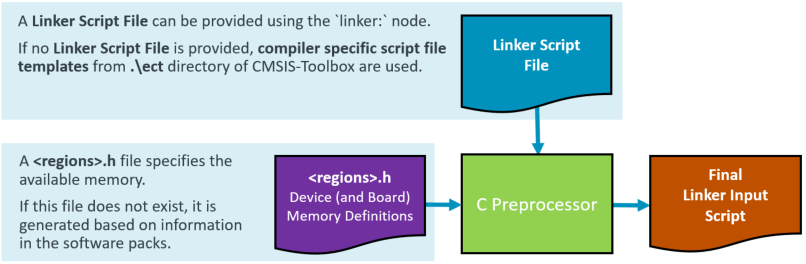
A standard C preprocessor is used for the Linker Script file when:
- the linker script file extension is
*.src. - the
linker:node contains aregions:header file or adefine:.
Otherwise, no preprocessor is used, and the Linker Script file is directly passed to the linker.
Note
- If the
linker:specifies ascript:orregions:files, the automatic Linker Script generation is disabled. - Some toolchains (for example GNU ld) support splitting a linker script into multiple files using an
INCLUDEdirective. Ensure that these included files are reachable by the linker (recommended is the use of relative paths in theINCLUDEdirective). For portable projects, prefer a preprocessed linker script (*.src) and include aregions:header.
Automatic Linker Script generation
The automatic Linker Script generation uses a Linker Script template and generates a <regions>.h file based on information from the software packs using the:
Both files, the Linker Script template and the <regions>.h are located in the RTE directory path \RTE\Device\<device>. The <regions>.h file name is extended with:
Bnamewhen the project context uses aboard:specification, i.e.regions_IMXRT1050-EVKB.hDnamewhen the project context only uses adevice:specification, i.e.regions_stm32u585xx.h.
Both files, the Linker Script template and the <regions>.h can be modified by the user as it might be required to adjust the memory regions or give additional attributes (such as noinit).
Note
For more information, refer to Create Applications: Configure Linker Scripts.
Linker Script Templates
The following compiler-specific Linker Script template files are copied to the \RTE\Device\<device> directory when no Linker Script exists. The files are located in the directory <cmsis-toolbox-installation-dir>/etc of the CMSIS-Toolbox.
| Linker Script Template | Linker control file for ... |
|---|---|
ac6_linker_script.sct.src |
Arm Compiler |
gcc_linker_script.ld.src |
GCC Compiler |
iar_linker_script.icf.src |
IAR Compiler |
clang_linker_script.ld.src |
CLANG Compiler (LLVM) |
Important
CLANG v21 (ATfE) uses picolibc initialization support that requires the linker symbols __bothinit_array_start and __bothinit_array_end. The current clang_linker_script.ld.src template defines these symbols around the pre-initialization and initialization arrays. When upgrading an existing project to CLANG v21 (ATfE), update any customized or previously copied CLANG linker script accordingly.
Generator Support
Generators, such as STM32CubeMX or MCUXpresso Config Tools, simplify the configuration for devices and boards. The CMSIS-Toolbox implements a generic interface for generators. Generators may be used to:
- Configure device and/or board settings, such as clock configuration or pinout.
- Add and configure software drivers, for example, for UART, SPI, or I/O ports.
- Configure parameters of an algorithm, such as DSP filter design or motor control parameters.
The steps for creating a *.csolution.yml application with a Generator are:
- Create the
*.csolution.ymlcontainer that refers to the projects and selectsdevice:orboard:(by usingtarget-types:) - Create
*.cproject.ymlfiles that are referred to by the*.csolution.ymlcontainer. - Add
components:to the*.cproject.ymlfile. - For components that have a
<generator-id>, run the related generator.
The Generator can add files, components, and settings to a project using the Generator import file (*.cgen.yml). The format of this file is similar to a software layer.
Use a Generator
An example that uses STM32CubeMX is provided in github.com/Open-CMSIS-Pack/csolution-examples. The ./CubeMX example is used below.
To list the Generator configuration of a *.csolution.yml use:
csolution CubeMX.csolution.yml list generators --active MyBoard@Debug --verbose
CubeMX (Global Registered Generator)                 # Name of the Generator
  base-dir: STM32CubeMX/MyBoard                      # Generator output directory for context listed below
    cgen-file: STM32CubeMX/MyBoard/CubeMX.cgen.yml
      context: CubeMX.Debug+MyBoard
To run the generator (in this case CubeMX) use:
csolution CubeMX.csolution.yml run --generator CubeMX --active MyBoard@Debug
Configure Generator Output
The Generator output directory and the name of the Generator import file (*.cgen.yml) can be configured using the node generators: as shown below.
  generators:
    options:
    - generator: CubeMX
      path: ../STM32CubeMX
      name: MyConfig
A Generator output configuration is useful for:
- Using a board layer that is shareable across multiple projects.
- Using different configurations across a
*.csolution.ymlproject.
Detailed Usage Instructions
These chapters explain how to manage device and board configuration in more detail:
Run and Debug Configuration
The CMSIS-Toolbox uses the information from the DFP and BSP to simplify the debugger configuration. It generates the file <solution-name>+<target-type>.cbuild-run.yml that contains for one target of a csolution project all information for run and debug. This file is used by pyOCD and the CMSIS Solution extension for VS Code to configure debug and programming features of the supported debug adapters.
An application can be composed of various project contexts and additional images. In addition the debugger along with parameters are specified in the *.csolution.yml file using the target-set: node.
Note
Refer to Run and Debug Management for further details.
Examples:
The following example configures the ST-LINK debugger for the project MyProject with build-type Debug:
  target-types:
    - type: MyBoard
      board: B-U585I-IOT02A                   # Board name
      target-set:
        - set:
          debugger:
            name: ST-LINK
          images:
            -  project-context: MyProject.Debug
A target set can combine project contexts with different build types. This allows the project being debugged to use Debug, while size-sensitive supporting images use Release.
The following example uses a CMSIS-DAP debugger with JTAG protocol and configures a multi-core application with two projects. The project core0 uses the build-type Debug. The project core1 uses the build-type Release.
  target-types:
    - type: Alif_AppKitE7
      board: Alif Semiconductor::AppKit-E7
      target-set:
        - set:
          debugger:
            name: CMSIS-DAP
            protocol: jtag

          images:
            - project-context: core0.Debug
            - project-context: core1.Release
Using pyOCD
A csolution project that uses target-set: to configure the debugger and select the images/projects and build-types should be build using the option --active to select the target in the format <target-type>[@<target-set>]. The cbuild command creates then a corresponding *.build-run.yml file that can be used with pyOCD version 0.37.0 or higher. This *.build-run.yml file contains all information to program and debug the application.
Example:
cbuild MyApplication.csolution.yml --active MyBoard                       # build application
pyocd load --cbuild-run MyApplication+MyBoard.cbuild-run.yml              # download image to target
pyocd gdbserver --cbuild-run MyApplication+MyBoard.cbuild-run.yml         # start GDB remote server
Using VS Code
With the VS Code extension CMSIS Solution version 1.54 or higher use the Manage Solution view to configure the debugger. You may then use the CMSIS Debugger extension for interactive debug or pyOCD in command line mode.
Device Configuration
Several DFP contain *.dbgconf files that configure device-specific debug and trace parameters. The CMSIS-Toolbox provides this configuration information in the *.cbuild-run.yml file for debuggers with Debug Access Sequence support.
The CMSIS-Toolbox creates the .cmsis directory in the csolution project directory and generates a default *.dbgconf file for each target, for example .cmsis/MyApplication+MyBoard.dbgconf. This file can be modified to reflect user settings.
An explicit user-managed *.dbgconf configuration file can instead be specified using the debugger: node in the *.csolution.yml file.
Native CMake Build Integration
Native CMake projects can be integrated into a csolution project without a *.cproject.yml file. The CMSIS-Toolbox configures and builds each project using the source directory, generator, configure options, and optional build target specified in the cmake: node.
CMake projects are listed under projects: in the *.csolution.yml file and participate in the solution's target-types: and build-types:. Their declared output images are included in the generated *.cbuild-run.yml file and can therefore be combined with images from other project contexts for programming and debugging.
The standard build commands also apply to native CMake project contexts:
cbuild setup MySolution.csolution.yml --active DualCoreDevice
cbuild MySolution.csolution.yml --active DualCoreDevice
cbuild MySolution.csolution.yml --active DualCoreDevice --clean
cbuild MySolution.csolution.yml --active DualCoreDevice --rebuild
The native project remains responsible for its CMakeLists.txt, toolchain setup, build targets, and generated files. CMSIS-Toolbox provides orchestration and records the declared images; it does not translate the native project into a *.cproject.yml file. Paths under images: identify outputs relative to the native project's context output directory.
Example:
solution:
  target-types:
    - type: DualCoreDevice
      device: Vendor::DualCoreDevice

  projects:
    - cmake:
        source: ./core0
        device: :Core0
        images:
          - image: build/core0.elf
            type: elf
For a complete application that integrates a native CMake project with CMSIS-Toolbox, refer to Arm-Examples/CMSIS-CMake.
West Build System Integration
The West build system is a project management system used primarily in the Zephyr ecosystem. The integration in the CMSIS-Toolbox acts as a "build orchestration wrapper" around CMake.
The CMSIS-Toolbox connects the west build command with the information of the CMSIS-Pack system as shown in the diagram below. For the selected compiler the related environment variables for the west build system are set. When combined with the VS Code CMSIS Solution extension, features such as project outline in the CMSIS View or "go-to-definition" with clangd are available.
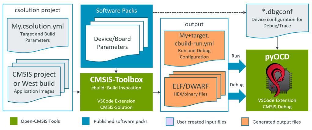
West projects are specified using the west: node under projects: in the *.csolution.yml file and can be managed with the target-types and build-types of the csolution project. Note that the sysbuild feature of west is not supported as the CMSIS-Toolbox manages already related projects.
The usual cbuild setup, build, clean, and rebuild operations also apply to West projects. During setup, the integration requests a compile_commands.json database from West for editor and language-server support. See West Integration for the command mapping.
Example:
solution:
  compiler: AC6

  packs:
    - pack: AlifSemiconductor::Ensemble@^2.0.0-0
    - pack: ARM::CMSIS

  target-types:
    - type: DevKit-E7
      board: Alif Semiconductor::DevKit-E7
      device: Alif Semiconductor::AE722F80F55D5LS
      variables:                            # west board selection
        - west-board: alif_e7_dk_rtss

      target-set:
        - set:
          debugger:
            name: J-Link Server
            port: 3333
            protocol: swd
          images:
            - project-context: rtss_he.Debug
            - project-context: rtss_hp.Release

  build-types:
    - type: Debug
      optimize: debug
      west-defs:                           # west defines
        - CONFIG_DEBUG: y
        - CONFIG_DEBUG_THREAD_INFO: y
        - SE_SERVICES: OFF
        - CMAKE_BUILD_TYPE: Debug

    - type: Release
      optimize: size
      west-defs:                           # west defines
        - SE_SERVICES: OFF
        - CMAKE_BUILD_TYPE: Release

  projects:
    - west:
        app-path: ./alif/samples/drivers/ipm/ipm_arm_mhuv2/rtss_he
        board: $west-board$_he
        device: :M55_HE
    - west:
        app-path: ./alif/samples/drivers/ipm/ipm_arm_mhuv2/rtss_hp
        board: $west-board$_hp
        device: :M55_HP
For a multi-board Zephyr example that includes debugging and CI workflows, refer to Arm-Examples/CMSIS-Zephyr.
MLOps Integration
An MLOps (Machine Learning Operations) system automates the process of generating and maintaining machine learning (ML) models. Often described as "DevOps for ML", it bridges the gap between data scientists who build ML models and embedded developers that integrate these models into real-world applications.
The CMSIS-Toolbox generates the file *.cbuild-mlops.yml as the interface between a csolution project and an MLOps system. It combines DFP information about the processor and NPU with project settings so that model conversion does not duplicate target-specific configuration.
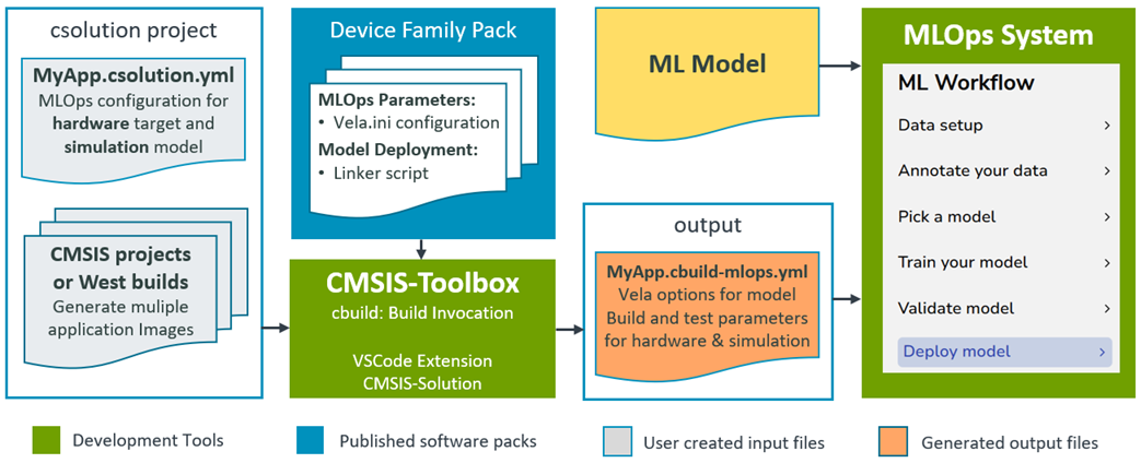
The *.cbuild-mlops.yml file provides information about:
- Processor type
- NPU type with MAC configuration
- Vela INI file and parameters (only for Ethos-U NPUs)
- Location of the
*.clayer.ymlfile that contains the ML model under development - Custom model properties, including simple values, lists, and grouped settings with additional levels
- Build information (using
cbuildwith hardware target) for testing on hardware - Build information (using
cbuildwith simulator target) for testing on FVP simulation models along with information for FVP invocation
The *.cbuild-mlops.yml file is designed for applications that use one or more ML models and optional NPUs. Custom properties in the model: node can describe framework-specific inputs as simple values, lists, or grouped settings with additional levels. This allows a model integration script to process several models or related artifacts in one workflow. When mlops: is used, the CMSIS-Toolbox generates the *.cbuild-mlops.yml file with the base name of the *.csolution.yml file in the same folder.
Model Integration Workflow
Model creation is separate from the application build. A typical command-line workflow is:
-
Generate the resolved MLOps information for the selected target:
bash
cbuild setup MyApp.csolution.yml --active SSE-320-U85@FVP-Test --packs
This creates
MyApp.cbuild-mlops.ymlwith the processor, NPU, Vela options, model metadata, AI-layer location, and test target information. -
Pass that file to the framework-specific model integration script:
bash
python create_ai_layer.py MyApp.cbuild-mlops.yml
The script performs model export or conversion and writes a complete AI layer, including the generated C/C++ model data and the
*.clayer.ymlfile with the required software components. The script is part of the framework integration, not the CMSIS-Toolbox. -
Build the application with the generated layer:
bash
cbuild MyApp.csolution.yml --active SSE-320-U85@FVP-Test
This is a normal application build and does not run the model conversion. After changing the model or target, repeat the setup and AI-layer creation steps before rebuilding.
Example:
MyApp.csolution.yml input:
solution:
   :
  mlops:
    description: ML model for detecting Rock/Paper/Scissors images
    npu:
      type: Ethos-U85           # Select NPU as the Alif E8 Device has multiple NPUs
    vela:
      system: RTSS_HE_SRAM_MRAM # Choose system configuration from Vela.ini file
      memory: Shared_Sram       # Choose memory configuration from Vela.ini file
    model:
      clayer: $AI-Layer$        # Layer that contains the ML model
      framework: ExecuTorch     # Custom metadata passed to the MLOps system
      source:                   # Lists support workflows with multiple models
        - models/rps_detector.pte
        - $Model-Source$        # Undefined variables produce an empty string
      settings:                 # Nested maps are also preserved
        delegate: Ethos-U
        quantize: true
    hardware:
      target: AppKit-E8-U85@HIL # Hardware target used for testing
    simulator:
      target: SSE-320-U85@FVP-Test # FVP target used for testing
    :
  # List different hardware targets that are used to deploy the solution.
  target-types:
    - type: AppKit-E8-U85
      device: AE822FA0E5597BS0
      board: AppKit-E8-AIML
      variables:
        - Board-Layer: $SolutionDir()$/Board/AppKit-E8_M55_HP/Board_HP-U85.clayer.yml
        - SDSIO-Layer: $SolutionDir()$/sdsio/usb/sdsio_usb.clayer.yml
        - AI-Layer: $SolutionDir()$/ai_layer/ai_layer.clayer.yml
      target-set:
        - set: J-Link           # Debug setup for desktop (IDE workflow)
          debugger:
            name: J-Link Server
            clock: 4000000
            protocol: swd
            start-pname: M55_HP
          images:
            - project-context: AlgorithmTest.Debug
        - set: HIL              # Debug setup for test automation (HIL workflow)
          debugger:
            name: ULINKplus@pyOCD
            clock: 10000000
            protocol: swd
            start-pname: M55_HP
            stdio:
              - pname: M55_HP
                mode: console
          images:
            - project-context: AlgorithmTest.Debug

    - type: SSE-320-U85 # Simulator (Cortex-M85 + Ethos-U85)
      board: SSE-320
      device: SSE-320-FVP
      define:
        - SIMULATOR
      variables:
        - Board-Layer: $SolutionDir()$/Board/Corstone-320/Board-U85.clayer.yml
        - SDSIO-Layer: $SolutionDir()$/sdsio/fvp/sdsio_fvp.clayer.yml
        - AI-Layer: $SolutionDir()$/ai_layer/ai_layer.clayer.yml
      target-set:
        - set: FVP-Test          # Debug setup for test automation (FVP simulation)
          debugger:
            name: Arm-FVP
            model: FVP_Corstone_SSE-320
            config-file: Board/Corstone-320/fvp_config.txt
          images:
            - project-context: AlgorithmTest.Debug
MyApp.cbuild-mlops.yml output. Paths are relative to the location of the *.cbuild-mlops.yml file (which is in the same directory as the *.csolution.yml file).
cbuild-mlops:
  description: ML model for detecting Rock/Paper/Scissors images
  processor:
    type: Cortex-M55
  npu:
    type: Ethos-U85
    macs: 256
  vela:
    ini: .cmsis/ensemble_vela.ini
    options: --accelerator-config ethos-u85-256 --system-config RTSS_HE_SRAM_MRAM --memory-mode Shared_Sram
  model:
    clayer: ai_layer/ai_layer.clayer.yml
    framework: ExecuTorch
    source:
      - models/rps_detector.pte
      - ""
    settings:
      delegate: Ethos-U
      quantize: true
  hardware:
    active: AppKit-E8-U85@HIL
    cbuild-run: out/MyApp+AppKit-E8-U85.cbuild-run.yml
    output:
      - file: out/AlgorithmTest/AppKit-E8-U85/Debug/AlgorithmTest.axf
        type: elf
  simulator:
    active: SSE-320-U85@FVP-Test
    cbuild-run: out/MyApp+SSE-320-U85.cbuild-run.yml
    output:
      - file: out/AlgorithmTest/SSE-320-U85/Debug/AlgorithmTest.axf
        type: elf
    model: FVP_Corstone_SSE-320
    config-file: Board/Corstone-320/fvp_config.txt
Using the information in the *.cbuild-mlops.yml file, the MLOps system can create the AI layer and execute tests on hardware or simulation targets.
Framework Integration Examples
The CMSIS-ExecuTorch workflow uses an isolated model/model.py. A new model can replace this file without changing the build environment. Its create_ai_layer.py script exports and delegates the model, selects the required ExecuTorch CMSIS components, and writes the ExecuTorch program as C source into the AI layer.
The CMSIS-LiteRT preview workflow applies the same interface to LiteRT. Its create_ai_layer.py consumes the Vela parameters, converts the model data to C source, and selects either the Ethos-U or CMSIS-NN kernel components for the generated layer.
Both examples keep target and NPU settings in the csolution project and pass framework-specific model parameters as custom keys under mlops.model:. This separation allows a framework pack to supply the integration script while the application supplies only its model and target configuration. For ExecuTorch with Zephyr, refer also to CMSIS-Zephyr-ExecuTorch.
Test on Hardware
Build and test the ML model (in context with the application) with these commands.
>cbuild MyApp.csolution.yml --active AppKit-E8-U85@HIL --packs
>pyOCD load --cbuild-run out/MyApp+AppKit-E8-U85.cbuild-run.yml
>pyOCD run --cbuild-run out/MyApp+AppKit-E8-U85.cbuild-run.yml --eot --timelimit 30
Test on Simulator
Build and test the ML model (in context with the application) with these commands.
>cbuild MyApp.csolution.yml --active SSE-320-U85@FVP-Test --packs
>FVP_Corstone_SSE-320 -f Board/Corstone-320/fvp_config.txt -a out/AlgorithmTest/SSE-320-U85/Debug/AlgorithmTest.elf --simlimit 30