|
Open-CMSIS-Pack
Version 1.7.60
Delivery Mechanism for Software Packs
|
|
Open-CMSIS-Pack
Version 1.7.60
Delivery Mechanism for Software Packs
|
Most Cortex-M devices rely on Arm Debug Interface (ADI) that specifies standard interface for accessing debug functionality on the processor. However due to implementation-specific variations it can still be challenging for debug tool vendors to provide reliable debugging experience for complex devices. Device vendors can use debug access sequences to customize the debugger behavior for a particular device.
Section Usage of debug access sequences provides working example flows that can be implemented in a debugger. By overwriting the predefined debug sequences it is possible to customize the debugger operation for a specific device. The syntax and available functions are described in details in Writing debug access sequences. This chapter explains the common cases that can be covered using debug sequences:
The examples provided are quite generic demonstrating the concept to follow when addressing a specific scenario. However actual implementation shall always take device specific behavior into account.
The debug configuration options available in the debug IDEs mostly cover quite generic scenarios applicable to a wide set of devices and architectures, for example whether to use reset for debug connection and what type of reset, whether to stop after debug connection or not and so on. Configure debug access describes how to use debug descriptions to specify the configuration options available for the device and how to pre-select the default values.
But often there is a need to provide developers with some debug configuration options that are very device-specific. This can vary from simple SWO pin and clock source selection for tracing to more complex bootloader configuration or secure debug provisioning and multi-core system debug.
The debugvars element allows to define custom global debug access variables. Their values can also be made configurable via a project-specific debug configuration file (*.dbgconf). It is recommended to implement this file with Configuration Wizard annotations to enable simple graphical configuration view. Predefined debug access sequences can be overwritten where needed and use the custom debug variables. If a user-defined global access variable is not specified in the *.dbgconf file, then the value provided in the variable definition in the pdsc file is applied.
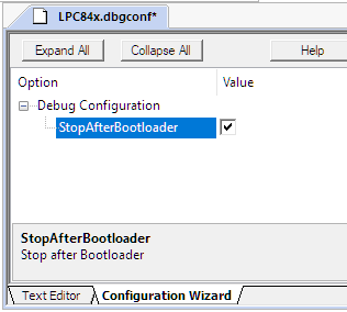
Documentation for the debugvars provides an example for trace SWO pin selection via a *.dbgconf file. Below is also an example that uses a custom global debug variable Dbg_CR for specifying whether the program shall stop after bootloader execution or not:
Use of debugvars in a pdsc file:
*.dbgconf file: source code
*.dbgconf file: Configuration Wizard view
In the same way custom debug variables can be used to provide configuration for device-specific debug registers that then can be programmed via debug sequences.
In some cases the debug access errors need to be ignored to support device-specific implemenation. For that the predefined debug access sequence can be overwritten by duplicating the original code with the error handling disabled in required places using predefined debug access variable __errorcontrol.
Below is an example for an NXP IMXRT1051 family:
In this implementation the standard system reset via AIRCR temporarily disables the DAP resulting in an access error. That could cause a debugger to disconnect. To overcome this the error handling is disabled before register write (__errorcontrol = 0x1;) and then enabled after it again. Additionally a delay is introduced (DAP_Delay(20000);) to allow reset to complete. The rest of the code is same as in the default ResetSystem implementation.
A common case that requires use of debug access sequences is trace configuration. Predefined debug access sequences have two trace-related sequences: TraceStart and TraceStop that are being called when trace is enabled in the project. The TraceStart sequence is executed at the end of the initial debug connection to the target and after device reset while TraceStop is executed at the beginning of debug disconnect.
By default these sequences are empty and often need to be implemented in the .pdsc file to support device-specific behavior, for example to differentiate configuration for 1-pin SWO trace and 5-pin ETM trace (TPIU).
If the parent sequences element specifies traceSetup=full, the trace-related debug access sequences are expected to perform the complete trace sink and trace data path setup and shutdown, rather than only device-specific additions to debugger-provided CoreSight handling.
For example:
Note that the code above uses following features allowed in debug access sequences:
TraceStart EnableTraceSWO ,EnableTraceTPIU Implementation of custom debug access sequences traceEnableSWO and traceEnableTPIU is a means to better structure the sequence implementations. Their content is highly vendor and device-specific. Common functionality of such sequences is to trace on the device, configure trace clock and assign trace pin(s). But the complexity of the code varies significantly depending on the device functionalities.
Below is a simple example of EnableTraceSWO for Microchip SAMS70 family, that also demonstrates the use of a user-defined global debug access variable (TracePCK3) configurable via a debug configuration file SAMx7.dbgconf. See Enable device-specific debug configurations for additional information about custom global debug variables and *.dbgconf file.
Some devices can require that trace clock is enabled already at DebugDeviceUnlock sequence to ensure that access to global trace components is available when reading the ROM table and processor features. In such cases corresponding functionality needs to be moved from TraceStart to DebugDeviceUnlock sequence and check if trace is enabled via the __traceout variable.
This section explains reset debug sequences for systems with a single CPU. Multi-core specifics are covered in Handle debug in multi-core systems.
Reset is an important part of debug operation and is used to bring the device into a known state from which debug connection can be reliably established. Reset also allows users to debug their code from the very beginning. In the typical case when user initiates a debug session the debugger connects to the device, and resets the processor to ensure its fresh start, and then stops the CPU before user application is started.
Sometimes it is needed to connect to a running target ("hot debug") without any resets performed when establishing a debug connection. Since there is no resets this is out of scope for the current section.
The figure below shows an example reset flow in a debugger (copied from Usage of debug access sequences):
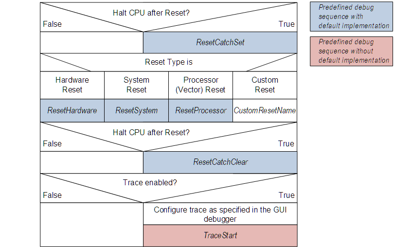
CPU halt and ResetCatchSet
In the flow shown above the debugger first decides whether to halt the processor after the reset or not. This decision depends on the project configuration but also on when and how the reset is requested (automatically by debugger during or after debug connect, or manually by user through IDE, etc.).
If processor halt after reset is needed then ResetCatchSet sequence is executed before performing the reset operation. Default implementation of ResetCatchSet enables and configures Cortex-M Reset Vector Catch functionality so that the core is stopped right after reset thus allowing users to debug the program from the very start. In some cases ResetCatchSet needs to be overwritten, for example for Support bootloader operation.
Reset types
There are 3 predefined reset types and a custom reset type that debugger chooses from when performing a reset. The choice depends on the project configuration and defaultResetSequence value. Corresponding reset debug sequence is executed to perform required reset type.
The reset types are listed below with details described in the referenced documentation.
After reset is performed and the processor is halted (on the breakpoint enabled in ResetCatchSet) the ResetCatchClear sequence is executed. The default implementation may need to be overwritten to support bootloader as explaine in Support bootloader operation.
Systems with built-in ROM bootloader often require special handling to ensure that debug is correctly started from the user application.
In particular the reset flow described in Implement reset for debug access most likely needs special adjustments for bootloader operation. After device reset the bootloader gets executed first. The debugger needs to take that into account and stop the processor with a breakpoint just before the application is started. For some devices this is also essential because debug can be disabled during bootloader execution for asset protection purposes.
The default implementation of ResetCatchSet sequence halts the core right after reset. This however would be before the bootloader is started and hence may be not relevant for application development or even not possible to debug if bootloader code is not available.
To overcome this problem the ResetCatchSet sequence needs to be overwritten in the .pdsc file of the Device Family Pack (DFP). In constrast to the default implementation the Reset Vector Catch shall be disabled allowing uninterrupted bootloader execution after reset. To halt the core before the application starts the sequence additionally sets a breakpoint at the Reset Vector, where the execution jumps to after bootloader is finished.
The code below gives an example for an Armv8-M system with the vector table placed at address 0x00000000:
After reset is performed and the processor is halted (on the breakpoint enabled in ResetCatchSet) the ResetCatchClear sequence is executed. There in addition to the default functionality we need to clear the breakpoint introduced in the customized ResetCatchSet sequence.
Below is a ResetCatchClear function for an Armv8-M core that corresponds to the ResetCatchSet sequence shown in Example 1: ResetCatchSet:
In some cases the ResetCatchSet sequence shall behave differently depending on where the obtained Reset Vector is located. Such differentiation can be introduced using XML <control> element. For example Cortex-M0/M0+/M1/M3/M4 cores have a FBP/BPU limitations that doesn't allow to set an FPB breakpoint for code memory above 0x20000000. For systems that have firmware located above this address (mostly in large external flash) the debugger can just rely on the Reset Vector Catch to stop right after reset and can't jump to the reset vector. Here is corresponding debug sequence:
Example 2: ResetCatchClear
The ResetCatchClear sequence from Example 1 can also be used with the Example 2: ResetCatchSet as there's no special handling additionally required.
Other modifications
Additionally the reset behavior can be made configurable per project via custom global debug access variables and a *.dbgconf file. See Enable device-specific debug configurations for additional details.
In some cases also the reset sequences (ResetSystem, ResetProcessor, ResetHardware) need to be adjusted to ensure proper bootloader handling. For example for debug authentication or bootloader configuration purposes. The actual implementation is very device and use case specific.
To correctly debug multicore systems, first of all the debug connection shall be correctly specified using debug. See Specify CPU debug connection for description and examples.
To achieve correct debug operation on a multi-core system often modification of the predefined debug sequences are required. The actual implementation very much depends on the particular system architecture.
The Usage of debug access sequences provides example flows for debugger operation. These flows shall be analyzed for particular system and different implementations may be required for each available core.
Recommendations described in previous sections such as error-handling, trace configuration, bootloader support can be applied for individual cores in the multi-core system as well. Using the Pname identifier in the sequence element it is possible to specify the debug access sequence for a particular core.
The most multi-core Cortex-M systems have their CPUs intended for running different applications and not for load balancing. For simplicity we consider further such an assymmetric (AMP) dual-core system. In this system the CPUs can have either equal roles or master-slave dependancy. The roles can also be either predefined or configurable.
Sections below explain additional use-cases specific for multi-core systems:
Multi-core devices often have quite unique reset systems that a debugger shall use correctly when connecting to a target and during debug operation. For that the default reset debug sequences (see Implement reset for debug access) need to be overwritten or require processor-specific implementations. Below is an overview for different reset types:
In the example above the reset functionality itself is implemented in the user-defined (custom) debug sequences ResetProcessor_CM0plus and ResetProcessor_CM4.
The same Pname identifier shall be used in sequence element as defined in the corresponding processor element ('CM0plus' or 'CM4' in this example).
Following the same concept the ResetCatchSet and ResetCatchClear sequences may need to be overwritten for individual cores, as reset vectors for different cores are located in different areas and hence the breakpoint for halt after reset shall be set differently. The approach is very similar to the one described in Support bootloader operation.
When debugging an application running on a processor in a multi-core system, it is often required to have special control over the processors in the system. For example in a master-slave system it may be desired to debug only the application on the slave. For that debugger needs to ensure that the slave is running independent from the master. Debug-related sequence DebugCoreStart can be used for that. Below is an example for NXP LPC4300 family, with ReleaseM0OnConnect is a configuration parameter specified via *.dbgconf as explained in Enable device-specific debug configurations.
