Debug descriptions allow silicon vendors to create tool-agnostic debug and trace configurations so that the development environment settings can be reduced to simple checkboxes for selecting for example either standard run/stop debugging or complex instruction tracing.
Concept
A set of standardized debug and trace methods are automatically executed by the debugger:
- Setting breakpoints and watchpoints
- Reading memory and registers
- Starting and stopping trace
Implementation-specific steps can be described using an XML syntax:
- Special hardware reset
- Trace buffer setup
- Patch silicon issues
Debug description elements
A complete debug description for a device consists of the following elements:
Debug access sequences
Debug access sequences define the activities of development tools to connect to a device using the debug channel for debugging, tracing, or flash programming. Several debug access sequences are predefined and executed in specific context. Refer to sequences for details.
Software development tools should implement Predefined debug access sequences. These predefined sequences can be overwritten by device specific sequences using the sequence element in the sequences section of the PDSC file. Additionally, a PDSC file can contain user-defined sequences, for example to reuse access sequence fragments:
Usage of debug access sequences
Predefined Debug Access Sequences are used in the following context:
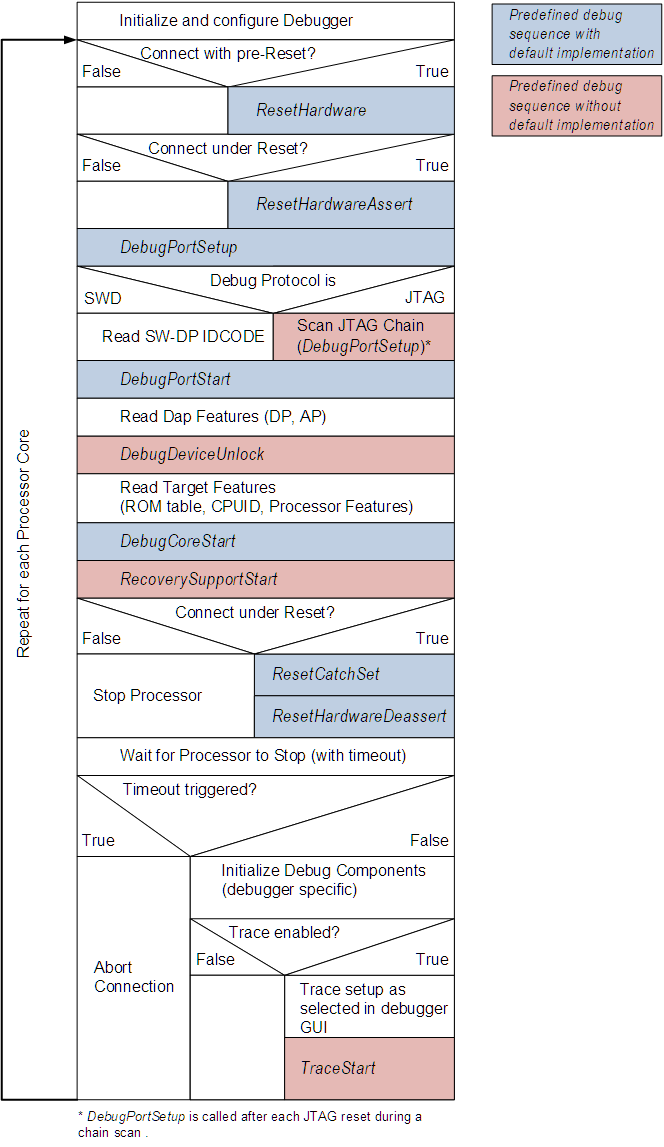
- Connect Debugger to Device is executed when debugging or flash programming with the target starts.
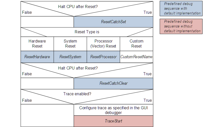
- Reset Device is executed to reset the target.
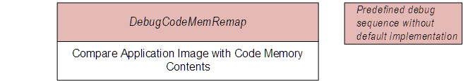
- Verify Code is executed to verify the content after flash programming.
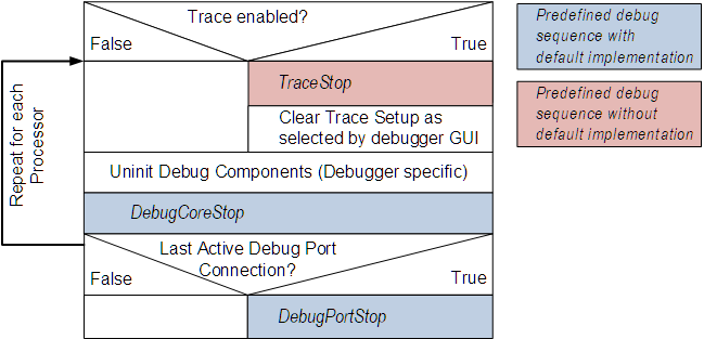
- Disconnect Debugger is executed when debugging or flash programming with the target stops.
The following diagrams show how the Debug Access Sequences are executed by a development tool.
Connect Debugger to Device is executed when debugging or flash programming with the target starts.
Reset Device is executed to reset the target.
Verify Code is executed to verify the content after flash programming.
Disconnect Debugger is executed when debugging or flash programming with the target stops.
Predefined debug access sequences
Debug access sequences are defined using the sequence element.
The table below lists the available predefined debug access sequences. Their default implementation is done in a development tool and gets executed by default. If PDSC file contains a user implementation of a predefined debug sequence (using sequence element) then it will override the default implementation and will be executed instead. Refer to Usage of debug access sequences for more information about the execution of these sequences.
For debug access sequences marked in ItalicRed, no default implementation exists. When using them in debug descriptions corresponding user implementation shall be done as well.
- Note
- Predefined debug access sequences read the System Control Space (SCS) of the processor and assume that the SCS base address is implemented as defined in the Armv6-M/Armv7-M/Armv8-M architecture reference manual.
| name= | Description |
| DebugPortSetup | Prepare the target debug port for connection; is executed before acquiring access to the debug port.
May include for example an SWJ-DP switch sequence as defined in the Arm Debug Interface (ADI) Architecture Specification.
This sequence must not contain debug port/access port register and target memory accesses other than:
- Reading the DPIDR debug port register to release an SWD connection from its line reset.
- Writing the TARGETSEL debug port register (SWD protocol v2).
|
| DebugPortStart | Connect to the target debug port and power it up; is executed after DebugPortSetup.
The parent debugport is default debug port for this sequence.
This sequence must not contain access port register and target memory accesses. |
| DebugPortStop | Power down and disconnect from target debug port.
Executed as last step during target disconnect unless another debugger connection to this port is active. The parent debugport is default debug port for this sequence.
This sequence must not contain access port register and target memory accesses. |
| DebugDeviceUnlock | Check if the device is in a locked state and unlock it. Use query command elements for user confirmation.
Executed after having powered up the debug port.
See example at User implementation of DebugDeviceUnlock sequence. |
| DebugCoreStart | Initialize core debug system.
Executed after having connected and powered up the default debug port for the connection. |
| DebugCoreStop | Uninitialized core debug system.
Executed as last step during disconnect before powering down any debug ports no longer required for concurrent connections. |
| DebugCodeMemRemap | Remap memory to execution location.
Executed before verifying memory content after flash programming. This is required to replicate a memory remap of a device bootloader (that is not executed during debug connection). |
| ResetSystem | Executes a system-wide reset without debug domain (or warm-reset that preserves debug connection) via software mechanisms, for example AIRCR.SYSRESETREQ. |
| ResetProcessor | Executes a local processor reset without peripherals and debug domains.
Uses a software mechanism (for example AIRCR.VECTRESET). |
| ResetHardware | Executes a system-wide reset without debug domain via the dedicated debugger reset line, e.g. nRST.
Debug confinguration and connection are typically preserved. But in some devices this is implemented as a power-on reset.
Specially useful in cases when device is locked and ResetSystem cannot be performed (for example debug pins are locked by the application). |
| ResetHardwareAssert | Assert a system-wide reset via the dedicated debugger reset line, e.g. nRST. |
| ResetHardwareDeassert | De-assert a system-wide reset via the dedicated debugger reset line, e.g. nRST. |
| ResetCatchSet | Executed before a target reset to configure the vector catch to stop code execution after the reset.
The implementation of ResetCatchSet requires an implementation of ResetCatchClear to free any hardware resources used for stopping the core. |
| ResetCatchClear | Executed after a target reset to free hardware resources allocated by ResetCatchSet. |
| FlashInit | Executed before starting a flash operation. |
| FlashUninit | Executed after a flash operation finished. |
| FlashEraseSector | Executed to erase a flash memory sector. |
| FlashEraseChip | Executed to erase all on-chip flash memory with target device specific erase technology. If this sequence is not implemented then a debugger can use FlashEraseSector to erase all flash memory. |
| FlashEraseDone | Executed after all flash memory erase operations are finished. |
| FlashProgramPage | Executed to program a single flash page. |
| FlashProgramDone | Executed after all flash programming operations are finished. |
| TraceStart | Enable target trace capture.
If sequences specifies traceSetup=legacy or omits the attribute, this sequence is executed before the debugger configures CoreSight trace components, e.g. after the initial target connection as well as after a system-wide reset.
If sequences specifies traceSetup=full, this sequence is expected to perform all trace sink and trace data path setup required by the device, and the debugger is not expected to configure CoreSight trace components using a priori knowledge.
See example at User implementation of TraceStart sequence. |
| TraceStop | Disable target trace capture.
If sequences specifies traceSetup=legacy or omits the attribute, this sequence is executed after the debugger disabled and powered down CoreSight trace components.
If sequences specifies traceSetup=full, this sequence is expected to perform all trace sink and trace data path shutdown steps required by the device. |
| TraceCapture | Prepare target trace for next capture run, e.g. by enabling the trace formatter or initializing embedded trace buffer data read/write pointers.
Typically executed before a debugger runs/steps the target processor. Or when manually starting a trace capture.
|
| TraceFlush | Flush out remaining trace bytes. This ensures all pending data is streamed off-chip, or drained into an on-chip trace buffer before the debugger reads it.
Typically executed after the target processor pauses after a run/step. Or when manually stopping a trace capture.
|
| RecoverySupportStart | Executed before step or run command to support recovery from a lost target connection, e.g. after a low power mode. |
| RecoverySupportStop | Executed after step or run command in context of the RecoverySupportStart sequence. |
| RecoveryAcknowledge | Debugger acknowledge after recovering from a lost target connection. Can be executed independently from a RecoverySupportStart sequence. |
Predefined default debug access sequences
The following sections the show the details of the predefined default debug access sequences.
DebugPortSetup
Prepare the target debug port for connection.
<sequence name="DebugPortSetup">
<block>
__var isSWJ = ((__protocol & 0x00010000) != 0);
__var hasDormant = __protocol & 0x00020000;
__var protType = __protocol & 0x0000FFFF;
</block>
<!-- JTAG Protocol -->
<control if="protType == 1">
<control if="isSWJ">
<control if="hasDormant">
<block atomic="1">
DAP_SWJ_Sequence(51, 0x0007FFFFFFFFFFFF);
DAP_SWJ_Sequence(16, 0xE3BC);
DAP_SWJ_Sequence(8, 0xFF);
DAP_SWJ_Sequence(64, 0x86852D956209F392);
DAP_SWJ_Sequence(64, 0x19BC0EA2E3DDAFE9);
DAP_SWJ_Sequence(12, 0x0A0);
DAP_SWJ_Sequence(6, 0x3F);
</block>
</control>
<control if="!hasDormant">
<block atomic="1">
DAP_SWJ_Sequence(51, 0x0007FFFFFFFFFFFF);
DAP_SWJ_Sequence(16, 0xE73C);
DAP_SWJ_Sequence(6, 0x3F);
</block>
</control>
</control>
<block atomic="1">
DAP_JTAG_Sequence(6, 1, 0x3F);
DAP_JTAG_Sequence(1, 0, 0x01);
</block>
</control>
<!-- SWD Protocol -->
<control if="protType == 2">
<control if="isSWJ">
<control if="hasDormant">
<block atomic="1">
DAP_SWJ_Sequence(51, 0x0007FFFFFFFFFFFF);
DAP_SWJ_Sequence(31, 0x33BBBBBA);
DAP_SWJ_Sequence(8, 0xFF);
DAP_SWJ_Sequence(64, 0x86852D956209F392);
DAP_SWJ_Sequence(64, 0x19BC0EA2E3DDAFE9);
DAP_SWJ_Sequence(12, 0x1A0);
DAP_SWJ_Sequence(51, 0x0007FFFFFFFFFFFF);
DAP_SWJ_Sequence(3, 0x00);
</block>
</control>
<control if="!hasDormant">
<block atomic="1">
DAP_SWJ_Sequence(51, 0x0007FFFFFFFFFFFF);
DAP_SWJ_Sequence(16, 0xE79E);
DAP_SWJ_Sequence(51, 0x0007FFFFFFFFFFFF);
DAP_SWJ_Sequence(3, 0x00);
</block>
</control>
</control>
<control if="!isSWJ">
<control if="hasDormant">
<block atomic="1">
DAP_SWJ_Sequence(51, 0x0007FFFFFFFFFFFF);
DAP_SWJ_Sequence(8, 0xFF);
DAP_SWJ_Sequence(64, 0x86852D956209F392);
DAP_SWJ_Sequence(64, 0x19BC0EA2E3DDAFE9);
DAP_SWJ_Sequence(12, 0x1A0);
DAP_SWJ_Sequence(51, 0x0007FFFFFFFFFFFF);
DAP_SWJ_Sequence(3, 0x00);
</block>
</control>
<control if="!hasDormant">
<block atomic="1">
DAP_SWJ_Sequence(51, 0x0007FFFFFFFFFFFF);
DAP_SWJ_Sequence(3, 0x00);
</block>
</control>
</control>
<block>
ReadDP(0x0);
</block>
</control>
</sequence>
DebugPortStart
Connect to the target debug port and power it up.
<sequence name="DebugPortStart">
<block>
__var SW_DP_ABORT = 0x0;
__var DP_CTRL_STAT = 0x4;
__var DP_SELECT = 0x8;
__var DP_STICKY_BITS = 0x000000B2;
__var JTAG_DP_STICKY_BITS_CLR = 0x00000032;
__var SWD_DP_STICKY_BITS_CLR = 0x0000001E;
__var powered_down = 0;
__var ctrl_stat_val = 0;
WriteDP(DP_SELECT, 0x00000000);
ctrl_stat_val = ReadDP(DP_CTRL_STAT);
powered_down = ((ctrl_stat_val & 0xA0000000) != 0xA0000000);
</block>
<!-- Check and clear sticky error bits -->
<control if="ctrl_stat_val & DP_STICKY_BITS">
<!-- JTAG specific part -->
<control if="(__protocol & 0xFFFF) == 1">
<block>
WriteDP(DP_CTRL_STAT, ctrl_stat_val | JTAG_DP_STICKY_BITS_CLR);
</block>
</control>
<!-- SWD specific part -->
<control if="(__protocol & 0xFFFF) == 2">
<block>
WriteDP(SW_DP_ABORT, SWD_DP_STICKY_BITS_CLR);
</block>
</control>
</control>
<!-- Check if DP is powered down and power it up if so -->
<control if="powered_down">
<block>
WriteDP(DP_CTRL_STAT, 0x50000000);
</block>
<!-- Wait for Power-Up Request to be acknowledged -->
<control while="(ReadDP(DP_CTRL_STAT) & 0xA0000000) != 0xA0000000" timeout="1000000"/>
<!-- JTAG specific part -->
<control if="(__protocol & 0xFFFF) == 1">
<block>
WriteDP(DP_CTRL_STAT, 0x50000F00 | JTAG_DP_STICKY_BITS_CLR);
</block>
</control>
<!-- SWD specific part -->
<control if="(__protocol & 0xFFFF) == 2">
<block>
WriteDP(DP_CTRL_STAT, 0x50000F00);
WriteDP(SW_DP_ABORT, SWD_DP_STICKY_BITS_CLR);
</block>
</control>
</control>
</sequence>
DebugPortStop
Power down and disconnect from target debug port.
<sequence name="DebugPortStop">
<block>
__var DP_CTRL_STAT = 0x4;
__var DP_SELECT = 0x8;
WriteDP(DP_SELECT, 0x00000000);
WriteDP(DP_CTRL_STAT, 0x00000000);
</block>
</sequence>
DebugCoreStart
Initialize core debug system.
<sequence name="DebugCoreStart">
<block>
__var SCS_Addr = 0xE000E000;
__var DHCSR_Addr = SCS_Addr + 0xDF0;
Write32(DHCSR_Addr, 0xA05F0001);
</block>
</sequence>
DebugCoreStop
Un-initialize core debug system.
<sequence name="DebugCoreStop">
<block>
__var SCS_Addr = 0xE000E000;
__var DHCSR_Addr = SCS_Addr + 0xDF0;
__var DEMCR_Addr = SCS_Addr + 0xDFC;
Write32(DHCSR_Addr, 0xA05F0000);
Write32(DEMCR_Addr, 0x00000000);
</block>
</sequence>
ResetSystem
Default implementation for ResetSystem debug access sequence that executes a system-wide reset via software mechanisms. Detailed description is provided in the table above.
<sequence name="ResetSystem">
<block>
__var SCS_Addr = 0xE000E000;
__var AIRCR_Addr = SCS_Addr + 0xD0C;
__var DHCSR_Addr = SCS_Addr + 0xDF0;
Write32(AIRCR_Addr, 0x05FA0004);
</block>
<!-- Reset Recovery: Wait for DHCSR.S_RESET_ST bit to clear on read -->
<control while="(Read32(DHCSR_Addr) & 0x02000000)" timeout="500000"/>
</sequence>
ResetProcessor
Default implementation for ResetProcessor debug access sequence that executes a local processor reset via software mechanisms. Detailed description is provided in the table above.
- Note
- This predefined debug access sequence is empty for Armv6-M and Armv8-M based processors.
<sequence name="ResetProcessor">
<block>
__var SCS_Addr = 0xE000E000;
__var AIRCR_Addr = SCS_Addr + 0xD0C;
__var DHCSR_Addr = SCS_Addr + 0xDF0;
Write32(AIRCR_Addr, 0x05FA0001);
</block>
<!-- Reset Recovery: Wait for DHCSR.S_RESET_ST bit to clear on read -->
<control while="(Read32(DHCSR_Addr) & 0x02000000)" timeout="500000"/>
</sequence>
ResetHardware
Default implementation for ResetHardware debug access sequence that executes a system-wide reset via dedicated debugger reset line. Detailed description is provided in the table above.
<sequence name="ResetHardware">
<block>
__var nReset = 0x80;
__var canReadPins = 0;
canReadPins = (DAP_SWJ_Pins(0x00, nReset, 0) != 0xFFFFFFFF);
</block>
<!-- Keep reset active for 50 ms -->
<control while="1" timeout="50000"/>
<control if="canReadPins">
<!-- Assert nRESET line and wait max. 1s for recovery -->
<control while="(DAP_SWJ_Pins(nReset, nReset, 0) & nReset) == 0" timeout="1000000"/>
</control>
<control if="!canReadPins">
<block>
DAP_SWJ_Pins(nReset, nReset, 0);
</block>
<!-- Wait 100ms for recovery if nRESET not readable -->
<control while="1" timeout="100000"/>
</control>
</sequence>
ResetHardwareAssert
Assert a system-wide reset line nRST.
<sequence name="ResetHardwareAssert">
<block>
__var nReset = 0x80;
DAP_SWJ_Pins(0, nReset, 0);
</block>
</sequence>
ResetHardwareDeassert
De-Assert a system-wide reset line nRST.
<sequence name="ResetHardwareDeassert">
<block>
__var nReset = 0x80;
__var canReadPins = 0;
canReadPins = (DAP_SWJ_Pins(nReset, nReset, 0) != 0xFFFFFFFF);
</block>
<!-- Wait max. 1s for nRESET to recover from reset if readable-->
<control if="canReadPins" while="(DAP_SWJ_Pins(nReset, nReset, 0) & nReset) == 0" timeout="1000000"/>
<!-- Wait 100ms for recovery if nRESET not readable -->
<control if="!canReadPins" while="1" timeout="100000"/>
</sequence>
ResetCatchSet
Configure the target to stop code execution after a reset.
<sequence name="ResetCatchSet">
<block>
__var SCS_Addr = 0xE000E000;
__var DHCSR_Addr = SCS_Addr + 0xDF0;
__var DEMCR_Addr = SCS_Addr + 0xDFC;
__var value = 0;
value = Read32(DEMCR_Addr);
Write32(DEMCR_Addr, (value | 0x00000001));
Read32(DHCSR_Addr);
</block>
</sequence>
ResetCatchClear
Free hardware resources allocated by ResetCatchSet.
<sequence name="ResetCatchClear">
<block>
__var SCS_Addr = 0xE000E000;
__var DEMCR_Addr = SCS_Addr + 0xDFC;
__var value = 0;
value = Read32(DEMCR_Addr);
Write32(DEMCR_Addr, (value & (~0x00000001)));
</block>
</sequence>
Examples of non-standard debug access sequences
This section provides examples of user-implemented predefined debug access sequences.
User implementation of TraceStart sequence
<sequence name="TraceStart">
<block>
__var value = 0;
value = Read8(0x40004D2A);
Write8(0x40004D2A, (value | 0x20));
value = Read8(0x40004D2C);
Write8(0x40004D2C, (value & (~0x20)));
</block>
</sequence>
User implementation of DebugDeviceUnlock sequence
<sequence name="DebugDeviceUnlock">
<block>
__var DAuthUserInput = 0;
__var DAUTHSTATUS_Val = 0;
__var DHCSR_Val = 0;
__var SecureDebugEna = 0;
__var SecureDebugAvail = 0;
__var DAuthVal = 0;
__var Status = 0;
DAUTHSTATUS_Val = Read32(0xE000EFB8);
DHCSR_Val = Read32(0xE000EDF0);
DAP_Delay(100000);
SecureDebugAvail = (DAUTHSTATUS_Val & 0x00000020) ? 1 : 0;
Status = ReadAP(0x0);
</block>
<control if="SecureDebugAvail" info="Configure Debug Authentication if Security Extensions available">
<block>
SecureDebugEna = ((DHCSR_Val & 0x00100000) || ((DAUTHSTATUS_Val & 0x00000030) == 0x00000030)) ? 1 : 0;
</block>
<control if="DAuthFixed">
<block>
DAuthVal = DAuthConfig;
</block>
</control>
<control if="DAuthFixed == 0">
<block>
DAuthUserInput = Query(1, "Enable Secure Debug?", 3);
</block>
<control if="DAuthUserInput == 3">
<block>
DAuthVal = 0xF;
</block>
</control>
<control if="DAuthUserInput != 3">
<block>
DAuthVal = 0x3;
</block>
</control>
</control>
<control if="SecureDebugEna">
<block>
Write32(0x50007000, DAuthVal);
</block>
</control>
<control if="SecureDebugEna == 0">
<control if="DAuthVal & 0x4">
<block>
Query(0, "Cannot configure Debug Authentication, secure debug disabled! Please reboot FPGA!", 1);
</block>
</control>
</control>
</control>
</sequence>
User implementation of hardware reset sequence
<sequence name="HWReset">
<block>
__var protType = __protocol & 0x0000FFFF;
</block>
<!-- JTAG variant-->
<control if="protType == 1">
<block atomic="true">
DAP_SWJ_Pins(0x00, 0x80, 0);
DAP_Delay(50000);
DAP_SWJ_Pins(0x80, 0x80, 0);
DAP_Delay(200);
DAP_JTAG_Sequence(6, 1, 0x7F);
DAP_JTAG_Sequence(1, 0, 0x01);
WriteDP(0x4, 0x50000F00);
WriteDP(0x8, 0x00000000);
WriteAP(0x00, 0x23000052);
WriteAP(0x4, 0xE000EDF0);
WriteAP(0xC, 0xA05F0001);
</block>
</control>
...
</sequence>
Calling sequences in a control block
...
<control if="siliconRevision >= 3" >
<block>
Sequence("SecurityUnlock");
Sequence("Set_JTAG_CTL");
Sequence("WaitIdleState");
Sequence("SetIDCODES");
</block>
</control>
...
Writing debug access sequences
To override a predefined sequence or to create a custom (user-defined) sequence, you need to write sequence elements. The following sections show how to use the built-in debug access syntax, expressions, and debug access functions to create custom sequences.
Debug access syntax rules
Debug accesses are described in block elements (within a debug access sequence or control element). The following syntax is used for this purpose:
- One or more statements have to be encapsulated in a block element.
- Each statement must begin in a new line and is terminated by a ; character.
- A typical statement consists of variable, followed by a = character and an expression, where the = character is an assignment of the expression result to the variable:
- Alternatively, a statement can be a sole expression without storing its result to a variable.
- Comments begin with two slashes (//) and end with a line break:
- Variables must be defined using the keyword __var. The definition must include an initialization of the variable:
- Variables can be defined only once within a scope. Scopes begin with entering a debug access sequence or a control element. They are extended to child control elements. Variables of a parent scope can be modified. Leaving a scope destroys all variables defined in it.
block elements do not begin a new scope. <sequence name="MySequence">
<block info="Block 1">
__var condvar = 1;
__var myvar1 = 5;
__var myvar2 = 0;
</block>
<control if="condvar">
<block>
__var myvar3 = 2;
myvar2 = myvar1 + myvar3;
</block>
</control>
<block info="Block 2">
myvar1 = myvar2 + 1;
</block>
</sequence>
- The debug access variables __dp, __ap, __apid, and __errorcontrol can be modified within a debug access sequence. An assigned value is held until leaving the sequence. Calling another sequence by the Sequence debug access function will push their values on a sequence execution stack. The values are restored when returning from such a call.
- The debug access variable __Result can be modified within a debug access sequence. Its value is held until the debug access sequence returns to the debugger. Hence its value is not pushed on a sequence execution stack when calling into another sequence by the Sequence debug access function.
- If the debug description contains access port elements
- then the debug access variable __ap must not be used. Use __apid instead.
- then the debug access variable __dp is only used for the ReadDP(), WriteDP(), and DAP_WriteABORT() debug access functions. All other debug access functions use the access port element that is referenced by __apid to determine the used debug port.
Expression rules
Expressions are used in various places to describe one of the following:
- A value as assigned in a debug access statement.
- A condition to use in the if attribute of a control element.
- A condition to use in the while attribute of a control element.
- A parameter to a debug access function as described below.
An expression may consist of the following:
- Constant numbers in decimal and hexadecimal representation (prefix 0x).
- Arithmetic operators such as +, -, *, /, and %.
- Bit-arithmetic operators such as &, |, ~, ^, >>, and <<.
- Comparison-operators such as ==, !=, <, >, <=, and >=.
- Logic operators such as !, &&, ||, and ==.
- Conditional expression operations like:
- Precedence of sub-expressions is indicated by brackets ((, )). C-like precedence applies if brackets are omitted.
- References to debug access variables for evaluating debug settings.
- Calls to debug access functions.
- Note
- All values used in expressions resolve to 64-bit unsigned integer values.
- All logic-operations and comparisons resolve to the value 1 if true, to 0 otherwise.
- XML prohibits the use of the characters &, <, and >. Use the corresponding XML entity names instead: &, <, and >.
Debug access functions
Debug access functions can be called in expressions in order to interact with the target device and the user. Parameters to functions can again be expressions.
By default, a debugger must abort the execution of a debug access sequence if a function call fails. However, this behavior can be controlled from a sequence by the __errorcontrol debug access variable.
The following table describes the existing debug access functions, their parameters and the debug access variables which are evaluated for the function call.
| Function | Description |
Sequence("name") | Execute a debug access sequence. Calling a sequence by this function causes the modifiable debug access variables __dp, __ap, __apid, and __errorcontrol to be pushed on a sequence execution stack. Returning from such a call will restore the state of these variables.
Parameters:
- name: Name of the sequence to execute. It must be enclosed by quotes.
Return Value:
Always returns 0.
Code Example:
Refer to Calling sequences in a control block
|
Read8(addr) | Read an 8-bit value from target memory. A device must support native 8-bit memory accesses for this function to succeed.
Parameters:
- addr: Memory address to read from.
Debug Access Variables:
If no access port elements exist:
- __dp: The debug port to use for this memory access.
- __ap: The access port to use for this memory access.
If access port elements exist:
- __apid: The ID of the access port element to use for this memory access.
Return Value:
The 8-bit value as read from target memory.
Code Example:
Refer to User implementation of TraceStart sequence
|
Read16(addr) | Read an 16-bit value from target memory. A device must support native 16-bit memory accesses for this function to succeed.
Parameters:
- addr: Memory address to read from.
Debug Access Variables:
If no access port elements exist:
- __dp: The debug port to use for this memory access.
- __ap: The access port to use for this memory access.
If access port elements exist:
- __apid: The ID of the access port element to use for this memory access.
Return Value:
The 16-bit value as read from target memory.
|
Read32(addr) | Read an 32-bit value from target memory. A device must support native 32-bit memory accesses for this function to succeed.
Parameters:
- addr: Memory address to read from.
Debug Access Variables:
If no access port elements exist:
- __dp: The debug port to use for this memory access.
- __ap: The access port to use for this memory access.
If access port elements exist:
- __apid: The ID of the access port element to use for this memory access.
Return Value:
The 32-bit value as read from target memory.
Code Example:
Refer to ResetSystem
|
Read64(addr) | Read an 64-bit value from target memory. A device must support native 64-bit memory accesses for this function to succeed.
Parameters:
- addr: Memory address to read from.
Debug Access Variables:
If no access port elements exist:
- __dp: The debug port to use for this memory access.
- __ap: The access port to use for this memory access.
If access port elements exist:
- __apid: The ID of the access port element to use for this memory access.
Return Value:
The 64-bit value as read from target memory.
|
ReadAP(addr) | Read a 32-bit value from an access port register.
Parameters:
- addr: AP register address to read from. Addresses larger than 0xF automatically cause an AP register bank switch.
Debug Access Variables:
If no access port elements exist:
- __dp: The debug port to use for this memory access.
- __ap: The access port to use for this memory access.
If access port elements exist:
- __apid: The ID of the access port element to use for this memory access.
Return Value:
The 32-bit value as read from the AP register.
Code Example:
Refer to User implementation of DebugDeviceUnlock sequence
|
ReadAccessAP(addr) | Read a 32-bit value from an address in the system's APv2 (ADIv6) top-level access port space.
Parameters:
- addr: Address within the system's top-level AP address space.
Debug Access Variables:
- __dp: The debug port to use for this access.
Return Value:
The 32-bit value as read from the top-level AP address.
Code Example:
Refer to DebugDeviceUnlock
|
ReadDP(addr) | Read a 32-bit value from a debug port register.
Parameters:
- addr: DP register address to read from.
Debug Access Variables:
- __dp: The debug port to use for this memory access.
Return Value:
The 32-bit value as read from the DP register.
Code Example:
Refer to DebugPortSetup
|
Write8(addr, val) | Write an 8-bit value to target memory. A device must support native 8-bit memory accesses for this function to succeed.
Parameters:
- addr: Memory address to write to.
- val: Value to write.
Debug Access Variables:
If no access port elements exist:
- __dp: The debug port to use for this memory access.
- __ap: The access port to use for this memory access.
If access port elements exist:
- __apid: The ID of the access port element to use for this memory access.
Return Value:
Always returns 0.
Code Example:
Refer to User implementation of TraceStart sequence
|
Write16(addr, val) | Write a 16-bit value to target memory. A device must support native 16-bit memory accesses for this function to succeed.
Parameters:
- addr: Memory address to write to.
- val: Value to write.
Debug Access Variables:
If no access port elements exist:
- __dp: The debug port to use for this memory access.
- __ap: The access port to use for this memory access.
If access port elements exist:
- __apid: The ID of the access port element to use for this memory access.
Return Value:
Always returns 0.
|
Write32(addr, val) | Write a 32-bit value to target memory. A device must support native 32-bit memory accesses for this function to succeed.
Parameters:
- addr: Memory address to write to.
- val: Value to write.
Debug Access Variables:
If no access port elements exist:
- __dp: The debug port to use for this memory access.
- __ap: The access port to use for this memory access.
If access port elements exist:
- __apid: The ID of the access port element to use for this memory access.
Return Value:
Always returns 0.
Code Example:
Refer to DebugCoreStart
|
Write64(addr, val) | Write a 64-bit value to target memory. A device must support native 64-bit memory accesses for this function to succeed.
Parameters:
- addr: Memory address to write to.
- val: Value to write.
Debug Access Variables:
If no access port elements exist:
- __dp: The debug port to use for this memory access.
- __ap: The access port to use for this memory access.
If access port elements exist:
- __apid: The ID of the access port element to use for this memory access.
Return Value:
Always returns 0.
|
WriteAP(addr, val) | Write a 32-bit value to an access port register. Addresses larger than 0xF automatically cause an AP register bank switch.
Parameters:
- addr: Memory address to write to.
- val: Value to write.
Debug Access Variables:
If no access port elements exist:
- __dp: The debug port to use for this memory access.
- __ap: The access port to use for this memory access.
If access port elements exist:
- __apid: The ID of the access port element to use for this memory access.
Return Value:
Always returns 0.
Code Example:
Refer to User implementation of hardware reset sequence
|
WriteAccessAP(addr) | Write a 32-bit value to an address in the system's APv2 (ADIv6) top-level access port space.
Parameters:
- addr: Address within the system's top-level AP address space.
Debug Access Variables:
- __dp: The debug port to use for this access.
Return Value:
Always returns 0.
Code Example:
Refer to DebugDeviceUnlock
|
WriteDP(addr, val) | Write a 32-bit value to a debug port register.
Parameters:
- addr: Memory address to write to.
- val: Value to write.
Debug Access Variables:
- __dp: The debug port to use for this memory access.
Return Value:
Always returns 0.
Code Example:
Refer to DebugPortStart
|
FlashWriteBuffer(addr, offs, len, mode) | Write flash buffer contents into target memory. A debugger fills the flash buffer before it executes a flash programming sequence.
Parameters:
- addr: Target memory buffer or register interface address to write the flash buffer contents. Must be a multiple of the number of bytes as specified by access size in parameter mode.
- offs: Offset into the flash buffer to start writing from. Must be a multiple of the number of bytes as specified by access size in parameter mode.
- len : Number of bytes to write to the target. If offs + len exceeds the flash buffer length set in variable __FlashLen, then the remaining bytes are filled with the pattern as specified by attribute filler of the block element. Must be a multiple of the number of bytes as specified by access size in parameter mode.
- mode: Target access mode. The following bit map applies:
- Bit 0..8: Debug access size. One of 8, 16, 32 and 64. The specified debug access size must be supported by the target debug access port.
- Bit 0: Additionally, set this Bit to 1 to increment the target address after each debug write access of the specified size.
- Bit 9..63: Reserved
Debug Access Variables:
If no access port elements exist:
- __dp: The debug port to use for this memory access.
- __ap: The access port to use for this memory access.
If access port elements exist:
- __apid: The ID of the access port element to use for this memory access.
Return Value:
Number of bytes written from flash buffer to target.
- Note
- Previous versions of the specification falsely named this function FlashBufferWrite. All known implementations of this specification correctly use FlashWriteBuffer already.
-
Previous versions specified to always return 0 in case of success. This was changed for consistency with other debug access functions handling buffers.
|
DAP_Delay(delay) | Debug probe command to wait for a specific delay.
Parameters:
- delay: Wait time in microseconds.
Return Value:
Always returns 0.
Code Example:
Refer to User implementation of DebugDeviceUnlock sequence
|
DAP_WriteABORT(value) | Debug probe command to write an abort request to the CoreSight ABORT register of the target debug port.
Parameters:
- value: 32-bit value to write into the CoreSight ABORT register.
Debug Access Variables:
- __dp: The debug port to use for this memory access.
Return Value:
Always returns 0.
|
DAP_SWJ_Pins(pinout, pinselect, pinwait) | Debug probe command to monitor and control the I/O Pins including the nRESET device reset line.
I/O Pin Mapping for pinout, pinselect, and pinwait:
- Bit 0: SWCLK/TCK
- Bit 1: SWDIO/TMS
- Bit 2: TDI
- Bit 3: TDO
- Bit 5: nTRST
- Bit 7: nRESET
The pinwait time is useful in systems where the nRESET pin is implemented as open-drain output. After nRESET is de-asserted by the debugger, external circuit may still hold the target Device under reset for a time. Using the pinwait time, the debugger may monitor selected I/O Pins and wait until they the expected value appears or a timeout expires.
Parameters:
- pinout: Value for selected output pins.
- pinselect: Selects which output pins will be modified.
- pinwait: Wait timeout for the selected output to stabilize. A debugger must extend this timeout to the closest possible time granularity.
- 0 = no wait
- 1 .. 3000000 = time in microseconds (max 3s)
Return Value:
The state of the I/O Pins at the end of this operation. If a debugger is not capable of monitoring the I/O Pins, it must return a value of 0xFFFFFFFF.
|
DAP_SWJ_Clock(val) | Debug probe command to set the clock frequency for JTAG and SWD communication mode.
Parameters:
- val: Maximum SWD/JTAG Clock (SWCLK/TCK) value in Hz.
Return Value:
Always returns 0.
Code Example:
Refer to ResetHardware
|
DAP_SWJ_Sequence(cnt, val) | Debug probe command to generate required SWJ sequences, e.g. for SWD/JTAG Reset, SWD<->JTAG switch and Dormant operation.
Parameters:
- cnt: Number of bits in sequence: 1..64. Larger sequences need to be implemented by multiple subsequent DAP_SWJ_Sequence calls. Such a sequence of DAP_SWJ_Sequence commands must be encapsulated in an atomic block to ensure correct execution.
- val: Sequence generated on SWDIO/TMS (with clock @SWCLK/TCK), LSB transmitted first.
Return Value:
Always returns 0.
Code Example:
Refer to DebugPortSetup
|
DAP_JTAG_Sequence(cnt, tms, tdi) | Debug probe command to generate a JTAG sequence with fixed TMS value and capture TDO.
Parameters:
- cnt: Length of the JTAG sequence (number of TCK cycles and TDI bits): 1..64
- tms: Fixed TMS value: 0..1
- tdi: Data generated on TDI with one bit per TCK cycle, LSB transmitted first.
Return Value:
Data captured from TDO with one bit per TCK cycle, LSB captured first and padded with 0s.
|
Query(type, "message", default) | Query user input. The sequence execution stalls depending on the used type. If the debugger runs in a batch mode, this function returns the value default.
Parameters:
- type: Query type. Can be one of:
- 0 : Query_Ok, displays an informative message which has to be confirmed by the user. This type allows the result OK.
- 1 : Query_YesNo, displays a query with the allowed results Yes and No.
- 2 : Query_YesNoCancel, displays a query with the allowed results Yes, No, and Cancel.
- 3 : Query_OkCancel, displays a query with the allowed results OK and Cancel.
- message: A constant string with the query message to display. It must not be an expression and it must be enclosed by quotes.
- default: The default value to return if the debugger runs in batch mode. See Return Values for a list of allowed values.
Return Value:
The result of the query. The user input maps to the following numbers:
- Error : 0
- OK : 1
- Cancel : 2
- Yes : 3
- No : 4
Code Example:
Refer to DebugPortSetup
|
QueryValue("message", default) | Query input value from user. The sequence execution stalls until the user has entered a value or canceled the query. This function returns the default value if the user canceled the query or if the debugger runs in a batch mode.
Parameters:
- message: A constant string with the query message to display. It must not be an expression and it must be enclosed by quotes.
- default: The default value to return if the user cancels the query or if the debugger runs in batch mode.
Return Value:
The queried value.
|
Message(type, "format", ...) | Outputs a message to a log window.
Parameters:
- type: Message type. Can be one of:
- 0 : Info, outputs an informative message.
- 1 : Warning, outputs a warning.
- 2 : Error, outputs an error and aborts the execution of the current sequence and its callers.
- format: A constant string with the message format. It must not be an expression and it must be enclosed by quotes. The string has the following format:
%[flags][width][.precision]specifier
- Specifiers:
- %u: 32-bit unsigned decimal integer.
- %llu: 64-bit unsigned decimal integer.
- %x: 32-bit unsigned hexadecimal integer, lower case letters.
- %llx: 64-bit unsigned hexadecimal integer, lower case letters.
- %X: 32-bit unsigned hexadecimal integer, upper case letters.
- %llX: 64-bit unsigned hexadecimal integer, upper case letters.
- %o: 32-bit unsigned octal integer.
- %llo: 64-bit unsigned octal integer.
- %b: 32-bit unsigned binary integer.
- %llb: 64-bit unsigned binary integer.
- %f: Single-precision (32-bit) floating point value.
- %Lf: Double-precision (64-bit) floating point value.
- %s: Constant character string. Must not be an expression.
- %%: Print % character.
- Flags:
- 0: Pad the displayed value with zeros instead of spaces if padding is required by the width option.
- Width: Minimum number of displayed characters. If width is less than the number of characters of the value, then the value is padded with spaces to the left.
- .Precision:
- Integer: Minimum number of displayed digits. Padded with zeros to the left if the value has less digits than specified with .precision.
- Floating Point: Number of displayed digits after decimal point. Defaults to 6 if not specified.
- Constant String: Maximum number of displayed characters.
- ... : Additional function parameters to replace format string specifiers. Each parameter can be a constant string, or an expression that resolves to an unsigned 64-bit integer. A parameter type must match the corresponding specifier type.
Return Value:
Always returns 0.
- Note
- For 32-bit specifiers the Message command must print the lower 32 Bit of a 64 Bit debug access variable.
|
LoadDebugInfo("file") | Loads DWARF debug information from an application executable.
Parameters:
- file: A constant string with the path to the executable. The path must be relative to the root folder of the pack and use the format path/name.extension. It must not be an expression and it must be enclosed by quotes.
Return Value:
Returns 0 after successful debug information load.
Returns 1 if debug information load failed.
|
| Functions for communicating with external tools |
BufferSet (buffID, buffOffset, count, size, value) | Fill a buffer with a specific value pattern. A new buffer of required size is created if it does not exist. An existing buffer is extended if it is too small.
Parameters:
- buffID: Numeric buffer ID. Must be a constant number.
- buffOffset: First byte in the buffer to start writing the specified value pattern. Must be a multiple of size.
- count: Number of size items to write with the specified value pattern.
- size: Size of a single item to set. Must be in the range of 1 - 8.
- value: Value pattern to set. The size least significant bytes of value are used as value pattern for writing the buffer.
Return Value:
Number of written bytes (written bytes * access size).
|
BufferGet (buffID, buffOffset, size) | Get a data item from the buffer.
Parameters:
- buffID: Numeric buffer ID. Must be a constant number. Function fails if buffer does not exist.
- buffOffset: Buffer offset in bytes to get the data item from. Must be a multiple of size.
- size: Size of a single item to get. Must be in the range of 1 - 8.
Return Value:
Data value of specified size at buffer offset.
|
BufferSize (buffID) | Get the current size of a data buffer.
Parameters:
- buffID: Numeric buffer ID. Must be a constant number.
Return Value:
Current buffer size in bytes. Return value is 0 if a buffer does not exist.
|
BufferRead (buffID, buffOffset, addr, length, mode) | Read data from target and store in buffer. A new buffer of required size is created if it does not exist. An existing buffer is extended if it is too small.
Parameters:
- buffID: Numeric buffer ID. Must be a constant number.
- buffOffset: First byte in the buffer to store the read data. Must be a multiple of the number of bytes as specified by access size in mode.
- addr: Target address to start reading from. Must be a multiple of the number of bytes as specified by access size in mode.
- length: Number of bytes to read from target. Must be a multiple of the number of bytes as specified by access size in mode.
- mode: The target access mode.
- Bit 0..8: Debug access size. One of 8, 16, 32 and 64. Specified debug access size must be supported by the target hardware. For example a DP register access must always be 32-Bit.
- Bit 0: Additionally set this Bit to 1 to increment the target address after each debug read access of the specified size.
- Bit 9..63: Reserved
Debug Access Variables:
If no access port elements exist:
- __dp: The debug port to use for this memory access.
- __ap: The access port to use for this memory access.
If access port elements exist:
- __apid: The ID of the access port element to use for this memory access.
Return Value:
Always 0. Function causes fatal error if not successful.
Code Example:
Refer to Calculating a hash sum
|
BufferWrite(buffID, buffOffset, addr, length, mode) | Write data from buffer into target.
Parameters:
- buffID: Numeric buffer ID. Must be a constant number. Function fails if buffer does not exist.
- buffOffset: First byte in the buffer to transfer into target. Must be a multiple of the number of bytes as specified by access size in mode.
- addr: Target address to start writing to. Must be a multiple of the number of bytes as specified by access size in mode.
- length: Number of bytes to write to the target. Must be a multiple of the number of bytes as specified by access size in mode. If size of valid buffer data is less than (buffOffset + length) then the function ends early and returns the number of actually written bytes.
- mode: The target access mode.
- Bit 0..8: Debug access size. One of 8, 16, 32 and 64. Specified debug access size must be supported by the target hardware. For example a DP register access must always be 32-Bit.
- Bit 0: Additionally set this Bit to 1 to increment the target address after each debug write access of the specified size.
- Bit 9..63: Reserved
Debug Access Variables:
If no access port elements exist:
- __dp: The debug port to use for this memory access.
- __ap: The access port to use for this memory access.
If access port elements exist:
- __apid: The ID of the access port element to use for this memory access.
Return Value:
Number of bytes written from buffer to target. Function causes fatal error if not successful.
- Note
- Previous versions specified to always return 0 in case of success. This was changed for consistency with other debug access functions handling buffers.
Code Example:
Refer to Calculating a hash sum
|
BufferStreamIn (buffID, buffOffset, length, path, mode, timeout) | Stream data from an external source, e.g. a file, into a buffer. A new buffer of required size is created if it does not exist. An existing buffer is extended if it is too small.
Parameters:
- buffID: Numeric buffer ID. Must be a constant number.
- buffOffset: First byte in the buffer to store the received data.
- length: Maximum number of bytes to stream in. Use value 0xFFFFFFFFFFFFFFFF to for example read a complete file of unknown size.
- path: Constant string value representing the source from which to stream data in. Refer to character sequences for path/file name place holders.
- mode: Specifies how to treat the data source in the specified mode.
- Bit 0..3: Format of the data source:
0 - Binary File
Others - Reserved
- Bit 4..7: Communication options for data source:
Reserved
- timeout: Timeout of file operation in microseconds. If 0, then synchronously wait for the operation to finish.
Return Value:
Number of bytes streamed into buffer. Can be less than length if the data source signals its end.
Code Example:
Refer to Calculating a hash sum
|
BufferStreamOut (buffID, buffOffset, length, destPath, destMode, timeout) | Stream data from a buffer to an external data sink, e.g. a file.
Parameters:
- buffID: Numeric buffer ID. Must be a constant number. Function fails if buffer does not exist.
- buffOffset: First byte in the buffer to transfer to the external data sink.
- length: Maximum number of bytes to stream out.
- path: Constant string value representing the destination to which to stream data to. Refer to character sequences for path/file name place holders.
- mode: Specifies how to treat the data source in the specified mode.
- Bit 0..3: Format of the data source:
0 - Binary File
Others - Reserved
- Bit 4..7: Communication options for data sink:
0 - Overwrite
1 - Append
Others - Reserved
- timeout: Timeout in microseconds. If 0, then synchronously wait for the operation to finish.
- This does not include file-system delays, e.g. between creation and visibility in a file browser. Use FilePathExists debug access function to wait for a new file to become accessible.
Return Value:
Number of bytes streamed to data sink.
Code Example:
Refer to Calculating a hash sum
|
RunApplication (appPath, arguments, workDirectory, timeout) | Run an external application.
Parameters:
- appPath: Constant string representing the application path. Refer to character sequences for path/file name place holders.
- arguments: Constant string with arguments to pass to the command line. Same placeholder character sequences apply as for appPath.
- workDirectory: A constant string with the work directory for the command line tool. An empty string means that the work directory is the current project folder. Same placeholder character sequences apply as for appPath.
- timeout: Timeout in microseconds
Return Value:
Application specific exit code.
Code Example:
Refer to Calculating a hash sum
|
FilePathExists(path, timeout) | Check if a path exists. If timeout is other than 0 then check the path until it becomes valid or until the timeout has elapsed.
Parameters:
- path: Constant string with the path to check. Refer to character sequences for path/file name place holders.
- timeout: Timeout in microseconds:
If 0, then the path is checked once before the function returns.
If other than 0, the function checks the path until it is valid or until the function times out. If timeout is hit while executing a check, then the function completes the check and returns its result.
Return Value:
0 - Path exists
1 - Path not found
Others - Reserved
Code Example:
Refer to Calculating a hash sum
|
- Note
- Target memory access functions must perform a debug access of the size indicated by their name. The target system must support debug accesses of this size.
- Results of all functions are casted to 64-bit unsigned integer values.
- Some target access functions determine the used debug and access port by the current values of the __dp and __ap, and the __apid debug access variables. If a target access requires a different debug or access port than the default ones, it must change these values. This change is held until finishing the sequence the change has occurred in.
- If the debug description describes access port elements then use of __dp is limited to the ReadDP(), WriteDP(), and DAP_WriteABORT() debug access functions. All other debug access functions determine the used debug port from the access port element referenced by __apid.
- If the debug description describes access port elements then __ap must not be used. Use __apid instead.
- A call to WriteDP() to change the DP SELECT register does not implicitly change the value of the debug access variables __ap or __apid. Those need to be explicitly updated to select a different AP for subsequent AP register and memory accesses.
- If a debug access function fails with an error, and if this error is not ignored by configuration of the __errorcontrol debug access variable, then the current sequence and its callers abort.
Debug access variables
Debug access variables hold 64-bit unsigned integer values and are used in debug access sequences to query debugger settings and states. They are read-only within a sequence except from a limited set of the pre-defined debug access variables. Use the debugvars element to specify additional user-defined debug access variables.
User-defined debug access variable names must not be reused for local sequence variables. To avoid name clashes, pre-defined debug access variables and local variables used by debugger-provided default sequence implementations should use the __ prefix. Local variables in DFP-provided sequences should not use the __ prefix, including when a DFP copies and adapts a default sequence shown in this specification. If a debugger implementation copies a default sequence from this specification, it should add the __ prefix to local variable names.
Table: Pre-defined Debug Access Variables
A debugger needs to support a set of pre-defined debug access variables. These are described in the following table.
| Variable | Access | Description | Value= |
__protocol | Read-Only | Debug protocol selection and parameters for target connection. | The following bit map applies:
- Bit 0..15: Type
- 0: Error
- 1: JTAG
- 2: Serial Wire Debug (SWD)
- 3: CJTAG
- Bit 16: SWJ-DP
- Bit 17: Switch through dormant state
- Bit 18..63: Reserved
|
__connection | Read-Only | Target connection configuration. | The following bit map applies:
- Bit 0..7: Connection type
- 0: Error or target is disconnected.
- 1: Connection for target debug.
- 2: Connection for downloading application to flash.
- Bit 8..15: Reset type
- 0: Error.
- 1: Hardware Reset (debugger reset line).
- 2: System Reset Request.
- 3: Processor Reset Request ("Vector Reset").
- Bit 16: Connection under Hardware Reset (debugger reset line)
- Bit 17: Hardware Reset is executed as a pre-connection reset (only used for debugger calls to
ResetHardware)
- Bit 18..63: Reserved
|
__dp | Read/Write | Debug Port selected for target accesses.
This variable is initialized when entering a pre-defined debug access sequence on a debug event. The initialization value is the __dp as defined for the used debug element.
If access port elements exist then use of __dp is limited to the ReadDP(), WriteDP(), and DAP_WriteABORT() debug access functions. | Debug port ID as specified in a debugport element or 0 if no debugport element exists. |
__ap | Read/Write | Access Port selected for target accesses.
This variable is initialized when entering a pre-defined debug access sequence on a debug event. The initialization value is the __ap as defined for the used debug element.
Must not be used if access port elements exist. Use __apid instead. | Access Port index. |
__apid | Read/Write | Access Port selected for target accesses.
This variable is initialized when entering a pre-defined debug access sequence on a debug event. The initialization value is the __apid as defined for the used debug element. | Access Port ID as defined in an access port element. |
__traceout | Read-Only | Activated trace outputs (sinks). Additionally holds information on the selected port width if a parallel trace port is enabled. | The following bit map applies:
- Bit 0: Serial Wire Output (SWO) Trace enabled.
- Bit 1: Parallel Trace Port enabled.
- Bit 2: Trace Buffer enabled.
- Bit 3..15: Reserved.
- Bit 16..21: Selected Parallel Trace Port size.
- Bit 22..63: Reserved.
|
__traceclockin | Read-Only | The frequency of the clock that drives the trace output component.
Can for example be used in combination with __traceclockout to calculate prescaler values for the output component. | Clock frequency in Hz. A value of 0 means that no frequency is provided by the debugger, e.g. because trace is disabled. |
__traceclockout | Read-Only | The frequency of the trace output signal.
Can for example be used in combination with __traceclockin to calculate prescaler values for the output component. | Clock frequency in Hz. A value of 0 means that no frequency is provided by the debugger, e.g. because trace is disabled or because the user did not specify it. In the latter case __traceclockout must be assumed to equal __traceclockin which effectively means a prescaler value of 1. |
__errorcontrol | Read/Write | Control variable for debug access error handling. All of its bit fields are intialized to 0 when entering a pre-defined debug access sequence because of a debug event. | The following bit map applies:
- Bit 0: Skip errors if set to 1. A debugger must continue the sequence execution.
- Bit 1..63: Reserved
|
__Result | Read/Write | Sequence result. A debugger sets this variable to 0 before it calls a sequence. The sequence implementation sets it to its result. | The following values apply:
|
__FlashOp | Read-Only | Type of the currently executed Flash operation. A debugger sets this value to 0 if the executed sequence is not part of a Flash operation. | The following values apply:
- 0: No flash operation
- 1: Erase
- 2: Program
- 3: Verify
- Other - reserved.
|
__FlashAddr | Read-Only | Start address for the current Flash operation. A debugger sets this value to 0 if the executed sequence is not part of a Flash operation. | Memory-mapped target address the currently programmed block is visible at. |
__FlashLen | Read-Only | Flash buffer length for the current flash operation. A debugger sets this value to 0 if the executed sequence is not part of a flash operation. | |
__FlashArg | Read-Only | Argument for the flash operation as specified in block. A debugger sets this value to 0 if the executed sequence is not part of a flash operation. | The argument encoding is specific to the debug description for the target device. |
Using external tools
Some functionality cannot be implemented by debug sequences, for example checksum/hash calculations or debug authentication. It is supposed to be provided or implemented by external tools or applications. To communicate with external tools, debug sequences currently provide input/output files. To create these files, buffers are used (see below). To run an external application, use the RunApplication function. To check the availability of an external resource (for example a file), use the FilePathExists function.
Buffer handling
Buffers are hidden inside the sequence engine. They can be accessed only via the following functions:
- For direct buffer access (for example for initialization or "memset" operations):
BufferSet, BufferGet, and BufferSize.
- For interaction with the target's memory:
BufferRead and BufferWrite.
- For external interaction via file stream:
BufferStreamIn and BufferStreamOut.
- Buffer sizes are adjusted as per operations. They cannot get smaller during a sequence execution, only larger.
- Buffers can internally have a size of '0', causing an error if calling BufferWrite/BufferStreamOut without having previously filled the buffer.
- Newly allocated buffer space is filled with 0's, e.g. for an initial call to BufferRead with a buffer offset.
- Buffers are only valid within the sequence creating them. When calling for example a "ChildSequence", it does not see buffers from the caller (even when using the same buffer ID). All buffer operations are only valid for buffers of the "ChildSequence".
Character sequences
For communication with external tools, you sometimes need to specify file names and paths to the files that contain the data to be exchanged. The following character sequences can be used as placeholders:
$P: Software project path including trailing slash#P: Software project path + project name, e.g. /project_path/project_name$L: Folder path of the main output file of a software project including trailing slash%L: Full path to the main output file of a software project including file ending$S: Path to the device support pack including trailing slash$D: Name of the selected device
- Note
- Characters '$', '#', and '%' must be duplicated to escape them, i.e. if a path contains the '$' character it must be written as '$$'.
Code Example: Calculating a hash sum
The following code example shows how to call an external tool to calculate a hash for an image file.
<block>
__var length = 0;
__var exitCode = 0;
__var fileExists = 0;
BufferRead (0, 0, 0x0080C000, 0xE0, (32|1));
BufferStreamOut(0, 0, 0xE0, "$P/SAML11_SHA256_BOCOR_input.bin", 0, 0);
exitCode = RunApplication ("$S/Tools/CalcSHA256.exe", "$P/SAML11_SHA256_BOCOR_input.bin --some-SHA256-parameters --out $P/SAML11_SHA256_BOCOR_output.bin", "$P", 10000000);
</block>
<control if="exitCode == 0" info="0 means OK">
<block>
fileExists = (FilePathExists("$P/SAML11_SHA256_BOCOR_output.bin", 5000000) == 0);
</block>
<control if="fileExists">
<block>
BufferStreamIn(0, 0xE0, 0x20, "$P/SAML11_SHA256_BOCOR_output.bin", 0, 10000000);
BufferWrite (0, 0, 0x0080C000, 0x100, (32|1));
</block>
</control>
</control>
<control if="(exitCode != 0) || (fileExists == 0)">
<block>
Message(2, "Error while creating hashsum. Aborting sequence.");
</block>
</control>